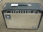
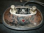
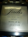
Servicing the JADIS JA30 MonoBlock Amplifier

June 14, 2020

JADIS JA30

The JADIS amplifier is a high-end domestic high-fidelity hand-wired creation from France. They are very expensive and also quite rare here in Australia. Production of the JADIS amplifier, and matching preamplifiers, began in the early 1980’s. The power amplifiers are built as MonoBlocks, so obviously a pair are required for a stereo system. JADIS products are clearly designed for the most fastidious music listeners, for whom money is no object (within reason). The power amplifiers are mostly designed to employ the thoroughly awesome KT88 power output valves (in ultra-linear configuration), which makes complete sense.
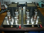
JADIS JA30

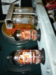
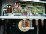
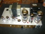
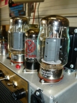
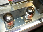
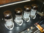
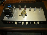
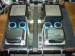
Our customer delivered a pair of the JA30 MonoBlocks to our workshop for a revalve (re-tube), and most importantly for replacement of all the valve sockets – a pair of octal and a pair of miniature 9-pin sockets for each MonoBlock. One only MonoBlock had unknown circuitry faults to be diagnosed and corrected as well. Each MonoBlock is loaded with a 12AU7/ECC82 and a 12AX7/ECC83 valve (tube), plus a pair of KT88’s. Each MonoBlock delivers 30 watts rms, operating in pure ‘Class-A’ (‘ultra-linear’ output transformer) configuration, with enormous over-engineered transformers.

JADIS JA30

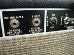
Each KT88 is cathode-biased (ie, self-biasing) and drawing 90ma with a HT voltage supply of +475V DC. Therefore, each KT88 is dissipating 40 watts at idle, plus 10 watts each heater filament. That’s pure Class-A for you.  But what a sound !! This pair of MonoBlocks appears to have been built in 1986, give or take. The extraordinary amount of heat being generated takes its toll on many of the components, over years of regular use. In particular, the valve sockets are no longer fit for purpose – they are barely functional.

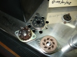
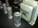
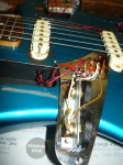
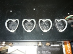
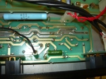
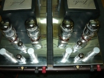
replacing the octal sockets

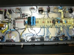
Our first choice of octal sockets would not fit on the chassis, so rather than make a mess we sourced an alternative with suitable dimensions. The miniature 9-pin valve sockets did not present any particular problems, they suit the standard 19mm hole, but the wiring and components had to be removed and reinstated in ‘layers’ (a bit like working on ‘Matchless’ amps), requiring extra time and a focused approach.
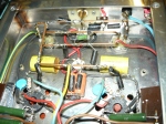
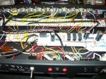
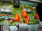
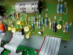
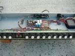
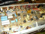
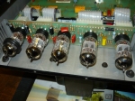
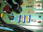
JA30 hand wiring

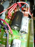
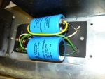
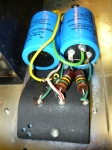
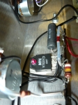
One only MonoBlock revealed destroyed screen grid resistors and cathode-bias components for the KT88’s. The primary reason for these failures turned out to be the cathode bypass capacitors, which under the extreme conditions went S/C (‘short circuit’), thereby removing bias for the KT88’s, resulting in ‘melt-down’. These capacitors are 150uF/200V axial units – actually not a common component at all. After some searching, we managed to source high-quality made-in-Sweden replacements, rated for  105 deg/C, from RS Components in Sydney. These are physically large, so were bedded down in silicone for stability.
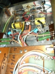
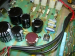
JA30 hand wiring

The two MonoBlocks required hours of bench time to restore to original performance, but our customer was very pleased with the end result. Both MonoBlocks tested identical in performance and specs, so the time and effort was well justified and this is also a tribute to the success and long term stability of the JADIS design. Our one very significant complaint about the JADIS company is that they refuse all requests for service information, schematics, etc. We understand that they are very protective of their designs, but this is ridiculous – it is just not practical to ship these monsters back to France every time they need a service.

In this case – because I have a background in the design and building of valve (tube) power amplifiers, I was able to reverse-engineer the aspects of the design that were important, but at a later point in time we had to service the matching preamp, which was truly a nightmare without a schematic. JADIS (and others) – please take note !! IR.


Service Centre for the Marshall JCM900 in Australia

August 18, 2019

Hello and welcome back to our blog. Today we will draw your attention to the fact that we have been servicing the JCM900 series of Marshall amplifiers, since their debut in the Australian marketplace, back in the 1990’s. In fact we were an authorised Marshall warranty repairer back in those times when Marshall quality control had really slipped very badly. An alarming number of JCM900’s (also Valvestates, etc) were returned for repair under warranty. The good news is once their problems were properly sorted out, they continued to give their owners reliable service.

In this blog, we are considering the Model 4100 100 Watt High Gain Dual Reverb (head), probably the most common of the several models of JCM900’s, which were available as 50W or 100W, but the 100W is the one we see most often. There were also “Master Volume’ models, plus a higher gain SL-X, all without the inclusion of reverb. There were problems with the supply of EL34 power output valves when these amps were first introduced, and so the first production amps were shipped with (Sovtek) 5881 output valves, with a sticker on the amp chassis to explain this. Later in the production run, when EL34 valve supplies were restored, Marshall reinstated these. If you have an earlier JCM900, we can restore your amp to EL34 power output with a relatively simple couple of MOD’s.

A significant departure in design philosophy from the previous JCM800 series amps, is the inclusion of solid-state preamp circuitry and clipping stages, combined with two 12AX7 valve gain stages and a 12AX7 EQ buffer stage. The reverb circuitry is completely solid-state. The exception to this is the SL-X model which is totally 12AX7 valve preamp circuitry. Therefore, as some of the High Gain Dual Reverb sound is being created in the solid-state preamp circuitry, the selection of preamp valves doesn’t seem to be as critical as in an all-valve high-gain circuit. The 12AX7’s are there to warm things up a bit, but they are not contributing high gain. The ‘normal’ channel employs LED’s as clipping diodes, and the ‘boost’ channel employs silicon diodes. The ‘lead gain’ control in the ‘boost’ channel goes all the way to ’20’, no doubt inspired by the 1980’s movie This is Spinal Tap. The phase-inverter and output stages are conventional Marshall valve circuits, although there are some changes from the earlier and very successful JMP & JCM800 designs.

What problems do we typically expect to see when a JCM900 is delivered to the workshop ?? Damaged pots & jacks would be high on the list. For whatever reasons, the Alpha split-shaft, PCB mounting pots are often damaged (ie, cutting in & out) to the point of requiring replacement. This is not a huge problem, we always have them in stock, and they are not expensive. The 9-pin (12AX7) valve sockets often are not doing their job, creating intermittent problems. Once again, these are not expensive – they are hand-wired, which is a good thing, but it is a labour intensive job to replace them. And of course, if the amp has had a hard-rocking life, a new pair or quartet of output valves (and power amp rebias) will be required.

Some of the 100 watt units will become unstable with a new set of valves. Some were possibly only marginally stable all along. There have been a couple of very basic valve amp design rules which have been overlooked by the design team, in the JCM900 series. Both the control grids and screen grids of each output valve must be fitted with a ‘stopper’ resistor, mounted as close to the valve socket as possible. When Marshall reinstated EL34 output valves, they installed 4 x 2.2K/5 watt screen grid resistors on the board for the 100 watt models. This is very good design practice but unfortunately, they are not really close to the actual sockets. The big mistake was with the control grid resistors – 1.5K was used in lieu of the traditional Marshall value of 5.6K, and it gets worse – two of them are mounted on the board, and only two at the sockets.

We would automatically install 4 x 5.6K (or higher) control grid resistors directly on the sockets, with all 100 watt JCM900 amps that we receive in the workshop. In the case of particularly unstable amps, we would increase the value of the control grid resistors. The great HIWATT amps of the 1970’s used 22K resistors in this position as standard, for example. These comments re grid ‘stopper’ resistors apply even more so to the original production run of made-in-China VOX AC100 amps, by the way.

What were the most common customer complaints (if any) about the JCM900 series amps, then and now ?? Ref the ‘master volume’ models, the original production run had very limited headroom – there was virtually no ‘clean’ sound at all. This was possibly down to the solid-state clipping circuitry ?? In any case, this issue was solved with the introduction of the SL-X ‘master volume’ model, which was all valve circuitry, except for the FX Loop. In the case of the ‘High Gain Dual Reverb’ models, overwhelmingly the complaint would be that the amps were really incredibly bright, requiring the ‘treble’ and ‘presence’ controls to be set counter-clockwise to compensate. We can assist with this issue, by implementing some simple power amp MOD’s (including: see the above paragraphs), resulting in a smoother top end response, and making the EQ controls useable again. These MOD’s do not reduce in any way the overdrive capability of these amps.

Thanks for checking in to the blog, Ivan Richards.

Service Centre for ‘PRS’ amps in Australia

September 17, 2017

PRS ARCHON 50 (head)

Hello and welcome back to the blog. We are now offering world-class (non-warranty) service & repairs to the range of valve (tube) guitar amplifiers from PRS Guitars, of Maryland, USA. We should point out that we have no official relationship with PRS, so we cannot accept any warranty repair claims without the endorsement of their Australian distributor.


PRS Archon 50

Our very first PRS amp repair was brought to us by new customer, Luke Denniss, from Central Coast NSW. This particular model is the Archon 50 in ‘head’ format. The Archon series of amps follows the tradition of offering a Fender inspired clean channel and a higher gain British voiced channel, footswitchable, plus a valve (tube) driven FX Loop as a bonus inclusion. PRS have chosen to employ a pair of the 6L6/5881 family of output valves for the 50 watt power amp.

PRS chassis interior

The clean channel offers one gain stage before the EQ and two gain stages after. The is before the signal path continues to the (series) FX Loop, and the PI (phase-inverter) stages. The lead (British) channel offers five gain stages prior to the 3-band passive EQ and master-volume. The end result for the lead channel is a very smooth, well controlled overdrive, with good decay characteristics. In order to keep the overdrive nice & tight, a fair amount of bottom end is sacrificed. If you are not looking for a high-gain preamp, then this amp is probably not for you.

output transformer is USA sourced ClassicTone

The assembly of the Archon employs a combination of boards and hand-wiring. Compared to the many production amps we have seen lately, this is a very practical and serviceable approach. This amp is very serviceable, and we heartily endorse that. The component layout on the boards very much follows the signal path, and for any experienced tech this is very easy to follow. What a contrast with some of the competition !

rebiasing the PRS is relatively straightforward

As you can see, whilst the power transformer is fairly nondescript, the output transformer is the ClassicTone model 40-18025, ie a 50 watt ‘plexi’ voiced transformer made in Chicago, USA. Luke’s amp was delivered to the workshop for a revalve. We removed & tested all valves, and only the output valve pair required replacement. Rebiasing this amp was straightforward, the power amp runs off a very healthy +475V, with no bias drift after our customary power output test & burn-in test.

PRS Archon 50

Many thanks to Luke for providing the subject matter for this week’s blog. IR.


Fender Jaguar (reissue) with wiring issues

July 2, 2017

a Jaguar on the bench

Hello again. As a bit of a departure from talking about amps & pedals, this week we talk about service & repairs to solid body electric guitars. To be more specific, a Fender Jaguar made-in-Japan reissue (serial # N070078), which was recently delivered to the workshop by regular customer Hannes Leak. We have been repairing, rewiring, upgrading pickups and so on, to solid body electric guitars for many years – however, this is the very first time we have struck a Fender Jaguar (or even played one), so they have been a bit of a mystery until now.


accessing the Jaguar controls

Hannes had recently acquired this instrument on the 2nd hand market, however it appeared that the switching & controls were not functioning. To a Jaguar novice, the arrangement of controls is somewhat confusing – there are four slider switches and two sets of volume & tone controls – none of this is actually labelled so you have to read up on Jaguars to understand the intended functionality.


the Jaguar pickup selector switches (plus mysterious tone switch)

Basically, only one sound was apparently available regardless of which way the slider switches were set. It was as if one pickup had gone open circuit. To access any of the wiring, the switching or the pickups, it is necessary to remove the pickguard, which necessitates loosening off all the strings so that first the bridge can be removed. Both pickups measured 6.1K ohms, so obviously they were not the problem. A Jaguar schematic diagram was sourced from the Seymour Duncan site, actually specific to the original 60’s model. However, just to make things even more confusing, the Japanese reissue does not follow the original colour code – all the wiring is either red or black.

Jaguar looking towards the bridge

Some wiring is easily accessible in the various body cavities, some wiring is routed directly underneath the pickups, which are screwed directly into the body. So, in order to trace which wire goes where, visual inspection is not enough – the wires need to be traced with a multimeter. To start with, we replaced the corroded output jack with a shiny new Switchcraft. The rhythm circuit, located on its own control plate on the upper part of the body, appeared to be where we were losing signal. The single slider switch engages the front pickup only when switched upwards, which has preset volume & tone circuits. When switched downwards, the player can select either front or back pickups, or both,  on the diamond shaped control plate on the lower part of the body, with a 3rd slider switch which attenuates the low frequencies for an even brighter tone. The output from this switch plate is controlled in the more conventional way by volume & tone controls located on the same control plate as the output jack. Phew !

the rhythm circuit control plate – note the thumbwheel rotation of the preset volume & tone controls

We next replaced the rhythm circuit slider switch, but this was not the complete solution to our problems. There did not appear to be any earth return path for the rhythm circuit – perhaps they were relying on the conductive paint which is obvious in all the cavities to complete the circuit, but this was no longer working. To solve the problem once and for all, we ran a wire from the rhythm circuit control plate through to the output jack plate. All functionality was now restored, although all the pots plus the three slider switches on the diamond shaped plate required a good clean. To reassemble, it is necessary to loosen off the strings once more, reinstall the pickguard and the bridge, and reinstall the three control panels. At the end of it all, the tone was what you might expect – very bright & clean (perfect for ‘surf’ instrumentals ?) with limited sustain compared to Strats & Teles, not really applicable to hard rocking styles, and with a much less bright tone from the rhythm circuit. The slider switches don’t feel as positive as the 3-way & 5-way rotary switches employed on Strats & Teles. We rather liked the tone from the neck pickup.

the reassembled Jaguar

Back in the day when the Jazzmaster & Jaguar were conceived, having preset ‘lead’ & ‘rhythm’ circuits made sense, as channel switching amps and pedalboards were still a long, long way into the future. To sum up for Jaguar  newbies such as Hannes & myself, this is how it all works:


Japanese Jaguar resissue

when the 2-way switch on the upper horn is in the UP position, you are playing through the RHYTHM circuit, neck pickup only, with volume & tone being controlled by the two thumbwheel pots on the upper horn

when the 2-way switch on the upper horn is in the DOWN position, you are playing through the LEAD circuit, which is controlled by the regular (ie rotary) volume & tone pots near the output jack, and the three separate 2-way switches located under the neck pickup, which are as follows (in order from closest to the neck) – neck pickup on/off, bridge pickup on/off, & high pass filter (ie bass cut) on/off.

a very sick PRO JUNIOR in the workshop

June 18, 2017

the Fender Pro Junior amp

Welcome back to the blog. Central Coast musician Justin – an established customer of ours, delivered to the workshop a very sick sounding Fender Pro Junior, which he had acquired on the ‘used’ market. These amps have been the subject of previous blogs, primarily from the point of view of upgrade MODs, which we will happily implement. This time we were confronted with a multiple fault condition scenario, which would require 3 hours bench time to completely resolve. Many of the problems in this amp were actually ‘introduced’ by some very dodgy ‘modding’ carried out by persons unknown to us.

the main high volts power supply cap is leaking but left in circuit

The fault conditions presented to us were as follows – amp crackling & distorting, amp was much too bright to such an extent that it was only useable with the tone control on zero, the V1 12AX7 always behaved as if microphonic, even after being changed repeatedly. We removed and tested all 4 valves – they all tested fine and were actually relatively new. Starting from the power supply and working back from there, the 1st thing you notice is that the high voltage power supply ‘reservoir’ capacitor is leaking electrolyte, obviously faulty manufacture, and should be replaced altogether. Unfortunately, somebody simply wired in a new capacitor across the faulty one, which was therefore still in circuit. We removed that horrible mess and installed a 47uF/500V capacitor by F&T.

the Pro Junior valve complement
the 9-pin sockets were no longer doing their job

The next very obvious concern was that the 9-pin valve (tube) sockets (V1 to V4 incl.) simply were not gripping the valve pins adequately any more, and not making a true connection. This is possibly a contributing factor to why V1 always appeared to be microphonic. We have struck this problem before, in the Pro Juniors & Blues Juniors (also the Peavey ‘Classic’ Series amps), possibly heat build up in the valve socket board is resulting in sockets with a limited service life, compared to other amps. In any case, we replaced the 4 sockets with nice shiny new ceramic body sockets, with exactly the same dimensions, they are readily available and are probably what manufacturers should be using in the first place.


all signal path capacitors had been modded to ‘orange drops’ resulting in awful tone

And now to the pre-amp circuitry and the reason for most of this amp’s ongoing issues. This is already a bright amp. The original 10-inch speaker, presumably by Eminence, has been replaced by a Jensen (reissue) ceramic magnet model. There is nothing at all wrong with this model – it does the job, but it is seriously bright, and this needs to be taken into account before carrying out MODs to the amp circuitry. Unfortunately this principle has been ignored, and every single capacitor in the signal path had been replaced by an ‘orange drop’ capacitor, plus all resistors had been replaced by metal film types.

new 9-pin sockets installed
board has been repaired & replaced

The above-mentioned changes alone would make this a very bright & brittle sounding amp, but add a very bright speaker into the mix and the result is unbearable – hence the need to run this amp with the ‘tone’ control fully counter-clockwise. To make matters worse, virtually every capacitor change has resulted in permanent damage to the copper side of the board (PCB), with too much heat & heavy-handed soldering technique causing tracks & pads to lift off the board altogether. This is the reason for the amp’s crackling & intermittent performance. The chosen strategy was to leave the resistors alone and concentrate on the signal path capacitors.

all signal path capacitors have been replaced with metalised polyester film

Each of the ‘orange drop’ capacitors was replaced with a metalised-polyester film cap, selected for it’s tried & true performance, based on previous experiences. In each case, the copper side of the board was restored to as close to original condition as possible, or else repaired with lengths of solid copper wire to complete the destroyed connections. One cap giving some H.F. pre-emphasis early in the circuit was deleted altogether, resulting in a more balanced sound (with this speaker). A total of 10 capacitors were replaced or deleted. The re-assembled amp was now completely stable with a good useable tone, within the limitations of a single tone control, ie there is no control over the bottom end or low mids. The Pro Junior tone control is quite powerful but limited to boosting or cutting the highs & upper mids.

In conclusion, working on printed circuit boards (PCBs) requires good soldering iron technique (plus a good temperature controlled iron), or else you are going to permanently damage the board, as was the case here. Best to practice by building a few kits or etc, before attempting to MOD valve amps. Amp modding has been going on for decades, usually to solve specific problems, or to add gain stages, FX Loops, etc. In recent times, the late Bill Machrone created a whole growth industry in amp modding with BillM Audio. Bill successfully targeted specific component upgrades to correct the original shortcomings in certain amp models, such as the Blues Junior. This focused approach makes complete sense, however the idea of replacing every single capacitor & resistor as suggested on some MOD websites is counter productive and prone to introducing problems that weren’t there in the first place.

Thanks for checking in to the blog. We continue to provide world-class service/repairs/MODs/upgrades/restorations to the Pro Junior, Blues Junior, Blues DeLuxe, Hot Rod DeLuxe, Blues DeVille & Hot Rod DeVille series of amps. Ivan R.

Approved service centre for Fargen Amps

June 4, 2017

Fargen Retro-Classic 1×12 combo

Welcome to our blog. We have recently been servicing the Fargen amps (USA) for our Newcastle/Hunter Valley customers, and we are pleased to advise that we are now the approved service agent, appointed by the new Fargen distributor in this region. Fargen amps were previously represented by Jacks Music of Newcastle, who arranged their own after-sales-service. Ben Fargen is primarily known for producing amp designs inspired by vintage Marshall amps (ie, prior to say 1973).

Fargen Retro Classic chassis

After Fargen & Jacks Music parted ways – our buddy Marc Saunders stepped in to provide local distribution. Marc delivered to the workshop one of his personal Fargen amps, the Retro Classic 1×12 combo (s/n 01653/2014). This model delivers about 25 watts from a pair of KT66 output valves with a GZ34 rectifier valve. We endorse this combination for some really cool vintage sounds. Marc’s amp was running way too hot, we are surprised the amp didn’t suffer any significant damage. The pair of KT66’s was seriously under-biased, drawing 95ma anode current (Ia) per KT66 at around 400V HT, with no signal ! We rebiased for a sensible & still toneful quiescent current of 45ma per KT66.

Fargen Retro Classic chassis

We don’t know if this was a mistake made by the Fargen factory prior to shipping, or made by the previous Australian distributors, or if the bias adjustment pot somehow accidentally got reset incorrectly, but it could have resulted in an expensive meltdown over time. We removed & individually tested all valves (standard procedure here) and found that the pair of KT66’s were still a close match, no need to replace at this time. We did find that V1 was testing microphonic, and replaced it with a selected low-noise JJ 12AX7. A power output test, burn-in test & earth test followed as always, the amp tested approx 25 watts into 8 ohms.

Fargen chassis underside

This 1×12 combo came standard loaded with a WGS Green Beret speaker, which is their “Greenback” inspired model, and seems to be a good match for old-school sounds. Strangely enough, the master volume control appears on the control panel ahead of the pre-amp volume control, not very intuitive but easy enough to get used to.


Fargen Retro Classic 25W

The 3-position Decade control reconfigures the pre-amp to give different shades of Marshall tone, with the ’68 setting also increasing pre-amp gain quite a bit. Many thanks to Marc Saunders for his continued custom, and for providing us with the subject matter for this week’s blog. IR.

A well kept secret: the Yamaha G100 212 II

April 2, 2017

Yamaha G100 212 II

Yes folks, one of the best kept secrets in the wide world of guitar amps is the late-70’s to early-80’s Yamaha G100 model (and similar) amps. They appeared in three series of models – series I, II & III – our pick would be series II which are very robust and obviously built to last the distance. Yamaha’s cosmetic approach is very conservative, but also quite distinctive.


check out the chassis – Yamaha G100 II

Yamaha obviously marketed these amps to compete primarily with the Roland JC120 series amps, and also the Fender ‘Twin Reverb‘. You can pick the Fender ‘Twin’ influence in the G100’s tonality, but in our opinion the G100 has a somewhat warmer tone and very powerful and flexible EQ. There are two channels, as you might expect in such an amp, each with volume treble/middle/bass controls and some ‘pull-on’ options. Common to both channels is (spring) reverb and a 3-knob parametric EQ.

Yamaha’s power amp module can be removed for repairs

This is a channel-switching amp. Channel A is warm and clean. Channel B has additional gain on board for some overdrive. Like any solid-state amp from this era, clean sounds are the main strength of the Yamaha. However, you could employ this amp effectively for most playing styles, excepting hard-rock, grunge and metal, etc. The power amp is modular and plugs into the power supply board. The module is fastened to the chassis via the large heatsink and is easily removed for repairs. The power amp design is quite an old-school 1970’s design, ie quite LO-FI, with a single-ended power supply which necessitates the use of a large output coupling capacitor to the speakers to block the DC voltage present at output (ie an electrolytic capacitor). Perhaps these are contributing factors to the Yamaha’s warmer sound ??

the G100 chassis is very serviceable

This example G100 was recently acquired by our regular customer, Ian Astill. We inspected the chassis and boards, as well as testing for electrical safety. The amp came up trumps apart from some very scratchy pots. Getting access to the pots for cleaning is not especially difficult. We removed the board behind the front panel and gave the offending pots a blast with FaderLube. These pots are the commonly used PCB mounting split-shaft/splined-shaft which facilitate a push-on style of control knob. Unfortunately, the shafts are often damaged and bent. Even worse sometimes the previous repairer has glued on some knobs, making removal without destroying the pot quite a challenge ! The bent shafts can be carefully straightened so there is no excuse for this approach.

parametric EQ on a guitar amp

Some say the original Yamaha speakers play an important part in this combo’s tonal response. If you are looking at acquiring one of these amps, this is probably something you should check out first. The parametric EQ is not easy to use – it takes time and effort and some experimentation to get a result. But the controls can be set for 12 o’clock and instead rely on the very functional channel (passive) EQ instead.


A well known user of these amps back in the day was American jazz guitarist Mike Stern. Americans Pat Metheny and Robben Ford are also said to have used these amps. I can recall seeing some Aussies using these amps back in the day including Rick Springfield. There is a rumour that these amps were designed by Paul Rivera, but the power amp design looks exactly like a standard Yamaha design, so who knows ?? The standard of assembly is very high, it’s little wonder these amps have survived so well, requiring very little in the way of service and repairs – mainly just damaged pots. IR.

MUSIC MAN 210-RD-100 guitar combo amp

March 28, 2017

210-RD-100

Welcome back to the blog. We continue to carry out service & repairs/restorations to the still popular original production amps from the Music Man company, built in the USA during the late 1970’s – early 1980’s era. This example is the 210-RD-100 model 100 watt 2 x 10 combo from the early 80’s period, owned since new by Peter Tos, and gigged heavily back in the day in Sydney’s nightclub scene.

front panel after new standby switch installed

The amp was delivered to the workshop with a broken standby switch, which is a 3-position toggle switch which selects either off (standby), high power or low power functions. Therefore, the switch needs to be a single-pole/double-throw (SPDT) with centre-off position, capable of switching high voltages. The standby switch achieves this functionality by routing higher or lower AC voltages to the voltage-doubler rectifier/power supply.

rear view new standby switch installed

In the high position, the power supply delivers approx 725V DC HT (no signal) to the anodes of the pair of 6L6GC output valves (tubes) !! No wonder this amp configuration easily achieves 100 watts audio output from a single pair of output valves. The screen grids are powered from half the HT voltage (otherwise they would certainly self-destruct). The valves are run very close to pure Class-B or in other words they are biased for very low current draw (no signal).

rebuilding the voltage doubler power supply

Having dealt with the primary problem, we knew from previous experiences we would need to check the condition of the high voltage electrolytic capacitors in the voltage doubler power supply. As expected, they had both ruptured and were no longer capable of doing their job. We replaced them with a pair of those very fine F&T 50+50uF/500V capacitors, bedded down in silcone for stability. The original capacitors have axial leads, so we have to hand wire the F&T vertical mounting units to the existing eyelet board.

another view of the voltage doubler eyelet board

The 500V F&T units in series give us a nice safety margin of 1000V DC maximum rating compared to approx 725V DC (as measured) high volts supply. We didn’t get a good earth test result, so we replaced the 240V 3-pin plug. The amps pots & jacks were cleaned with FaderLube & DeOxit, respectively. The Music Man amps were known primarily for their clean (“enhanced” Fender-style ??) tones, and this model is no exception. The overdrive channel produces what could be best described as 80’s distortion tones, which is nothing to get too excited about. The channel switching arrangements work very well. The original footswitch unit still works fine !! The 3-band EQ plus bright deep switches are shared by both channels.

the only valves in this amp – a pair of 6L6GC output valves

You may have noticed there are only two valves (tubes) in this amp design – the pair of 6L6GC output valves ! There are no pre-amp valves – the gain & signal shaping functions are performed by IC/op-amp’s. Even the phase splitting function to provide a pair of drive signals to the output valves, is performed by IC’s. How can an IC provide the level of drive signal to a 6L6GC valve you might wonder ?? Well, it’s achieved by configuring the 6L6’s in grounded grid mode of operation, whereby the drive signal is applied to the cathodes of the 6L6’s, utilising a pair of small NPN power transistors.

the well designed board still all original, as are the pots & jacks

The control grids still have a bias voltage applied, but they are grounded as far as signal is concerned. This arrangement works quite well, although you miss the warmth & colour of a valve phase-splitter stage. The only drawback that we have seen with this configuration in a guitar amp is that in the event of a catastrophic failure of an output valve, the drive transistors will surely be destroyed. The earlier 1970’s Music Man amps utilised a 12AX7 valve for the driver/phase splitter stages. Those amps are naturally considered more desirable, but lack the channel switching functionality. Thanks – IR.

the ruptured pair of high voltage filter capacitors

(the original footswitch still works fine !)

Restoration of an original Peavey 5150 EVH model amplifier

December 17, 2016
the 5150 head after the big clean up

the 5150 head after the big clean up

We recently received at the workshop one of the original Peavey 5150 dual channel high gain amps, which were the result of Mr Eddie Van Halen partnering with Peavey amps to produce his own signature model. In more recent times, Eddie has chosen to collaborate with Fender to launch his very own brand: EVH. This particular example of the 5150 reached us in very poor condition, with virtually no level from the rhythm channel and very low level from the lead channel. No serious service work had been carried out on the amp for years.

a total of five 12AX7 preamp valves (tubes)

a total of five 12AX7 preamp valves (tubes)

After a big clean up we removed all valves for testing and assessment. Most of the pots (potentiometers) were extremely scratchy and cutting in & out at certain points on their sweep, ie not at all useable, so we gave them a thorough cleaning with FaderLube. Only two of the five pre-amp valves (tubes) tested satisfactory, the others testing low gain and very microphonic. In the 5150 design, there is so much gain in the circuitry, far more gain than most styles of guitar playing would ever require, that wideband noise & microphony become major issues. Therefore, we have to carefully select the 12AX7 valves to be installed, and perhaps also select specific valves for specific positions in the signal path, ie V1 to V5 inclusive. You will notice in the photograph that we added rubber rings to V1 to provide additional dampening. The pre-amp valves are accessed by removing a cover on the rear panel.

octal sockets 'pop rivetted' to chassis

octal sockets ‘pop riveted’ to chassis

Only two of the quartet of Sovtek 5881 output valves tested satisfactory, but we were able to match up a quartet of 5881’s using a pair ex-stock. The wafer base Sovtek 5881 valves work quite well in amps like the 5150, as the tone of the amp is really being produced in the high gain pre-amp. Carrying out a quick power output test with our matched quartet of 5881’s installed, we observed a very asymmetrical waveform on the oscilloscope, indicating that possibly one 5881 was not contributing to the output. The next logical step would be to remove the output valve board from the chassis to examine it for damaged PCB tracks, octal sockets or associated components. We discovered that the board is fastened in place by ‘pop riveting’ the octal sockets to the chassis. HUH ?? It’s bad enough that the output valves are mounted to a PCB, but the only way to remove the PCB is to drill out the ‘pop rivets’ with the obvious danger of small bits of metal going everywhere under the chassis. This really is bad design practice (not Eddie’s fault though) !

the underside of the output valves PCB

the underside of the output valves PCB

Fortunately, in this case we were able to prove that the screen grid resistor for one single 5881 had gone O/C (open circuit) and it just so happened to be on that area of the board which was easily accessible from the ‘copper’ side of the PCB. In other words, we could replace this failed component without removing the PCB. You have to get lucky once in a while ! We chose to install a 100 ohm 7 watt ceramic body resistor designed for harsh conditions, as per the photo.

creating an adjustable bias supply

creating an adjustable bias supply

OK – so far we have cleaned the cab & chassis, inspected inside the chassis, cleaned the scratchy pots, replaced valves as required, corrected a fault on the output valve PCB & replaced a damaged 240V 3-pin plug. The remaining tasks are rebias the output valves, final power output test & electrical safety test. With this quartet of 5881’s, the amp is way overbiased with each 5881 only drawing about 12ma. Unfortunately the bias voltage is fixed at the factory at an arbitrary level which makes little sense. HUH ?? The only plausible explanation I can come up with for this decision is that Peavey marketing wanted you to buy their branded sets of output valves for these amps.

the 5150 power supply

the 5150 power supply

Consulting the 5150 schematic revealed that we could replace the final (fixed) 15K resistor in the bias supply (R68) with a 25K trimpot. R68, for whatever reason was covered in the hot glue applied at the factory, so we had to clean up that area of the main board, to enable us to snip off the resistor leads. Then we could connect leads from the trimpot to the final bias filter capacitor, before bedding down the trimpot in a blob of silicone. We set the trimpot to about 14K, ie slightly less than R68 measured, which was a good starting point for rebiasing the amp to a reasonable current draw. Power output was measured at over 100 watts into 16 ohms @ the onset of clipping.

5150 loaded with 5881 valves (tubes)

5150 loaded with 5881 valves (tubes)

We last discussed the 5150 series of amps in our blog do we cater for the metal head ? published Sept 2011. At that time the 5150 II was the model generally given the thumbs up by our metal addicted customers. Our favourite MOD for these models is the installation of a 10 Henry filter choke in the +500V DC power supply, manufactured by Mercury Magnetics, which cleans up the DC power very effectively. We no longer carry out warranty work on Peavey products, but we will continue to provide world-class service & repairs to your favourite old Peavey EVH amps and the Classic 20/30/50 series of amps. Thanks for checking out our blog. IR.

Service centre for “65 Amps” in Australia

December 11, 2016

65-amps-p1020689Hello and welcome back to the blog after a long break. We are now offering world-class (non-warranty) service & repairs to the range of valve (tube) amplifiers from 65 Amps guitar amplification of California, USA. We should point out that we have no official relationship with 65 Amps, so we cannot accept any warranty repair claims without their endorsement.

Lil' Elvis chassis - note the high-quality transformers by Mercury Magnetics

Lil’ Elvis chassis – note the high-quality transformers by Mercury Magnetics

Our customer, singer/songwriter Shane Nicholson delivered this “65 Amp” to our workshop for a general service & revalve. This model is called the Lil’ Elvis  and is a 1×12 combo of around 12 to 15 watts output, loaded with the very fine Celestion G12H30 70th Anniversary speaker. The valves (tubes) employed in this design are as follows: 3 x 12AX7 for the preamp, tremolo & PI stages, 2 x EL84 output valves (cathode-bias) for the power amp, plus a 6CA4 rectifier. The latter choice indicates there will be considerable sag/compression (ie similar in effect to the famous Marshall 18 watter).

chassis layout and wiring - not as obsessively neat as you might expect but very serviceable indeed

chassis layout and wiring: not as obsessively neat as you might expect but very serviceable indeed and superior to any PCB based amp in that regard

The circuit design of the Lil’ Elvis appears to incorporate design elements inspired by several vintage American amplifier designs, including the Fender Princeton and the simpler Ampeg models, featuring a single passive tone control. The 2nd 12AX7 stage is unusual – a bit like adding in a cathode-coupled phase-inverter into the signal path, prior to the actual split-load phase-inverter. This stage no doubt contributes to the unique tonal qualities of the Lil’ Elvis. The valve-generated tremolo is very effective. A passive FX Loop (ie a series loop) is incorporated into the design in such a way that it does not degrade the signal path with additional circuitry. However, if your FX device requires to be driven by a low-impedance source, then this loop will not be suitable.

65-amps-p1020685The “65 Amps” Bump circuit gives a significant boost, primarily to the mids and lows. You would probably set this one way or the other prior to playing or recording a song, rather than footswitching, due to the size of the boost and the fact that there is a very obvious “pop”, as the switching appears to be changing DC conditions for one of the gain stages, as well as increasing the gain. The cosmetic appeal of the amp is very distinctive. We are glad to see the cabinet is of sufficient proportions to give a reasonable low frequency response, ie this is not a ‘boxey’ sounding amp like some of the competition.

65-amps-p1020687We gave the amp chassis a good appraisal, with power output test, electrical safety test etc. A full revalve was called for but there were no other issues, all good !  65 Amps are evidently rather precious about which brands of valve (tube) go into each position, but we tried the Tung Sol (current production) versions in each case (except the 6CA4) and it sounded very good with that choice, although that brand might not be the best choice in every amp that is out there – we have to keep an open mind.

NTE2973 mosfet device

NTE2973 mosfet device

Finally, the “master” control, in spite of the hype on the website, is actually a power amp attenuator which works by reducing (attenuating) the high voltage supplied to the preamp and output valves (excepting of course the tremolo oscillator). The design is similar to that used in a number of amps, including our own 10 watt EL34se single-ended model, employing the NTE2973 mosfet device. It works very effectively, but as we have said before, it does inevitably change tone and dynamics at the lower settings. It is still a good feature to have with lower powered amps, which will often be used in home studios, etc.

Thank you again, Shane, for your continued custom. We look forward to providing world-class service and repairs to more 65 Amps models in the future. IR.