
Orange Graphic 100
Welcome back to the blog ! This week we look at a major overhaul to a battle-damaged classic from around 1971 – the Orange ORS100 “pics-only” head. Our very good customer David Challinor, guitar & vocals from the band Sounds Like Sunset, had recently acquired this vintage masterpiece, but in its existing condition the amp was quite unstable and of dubious electrical safety.
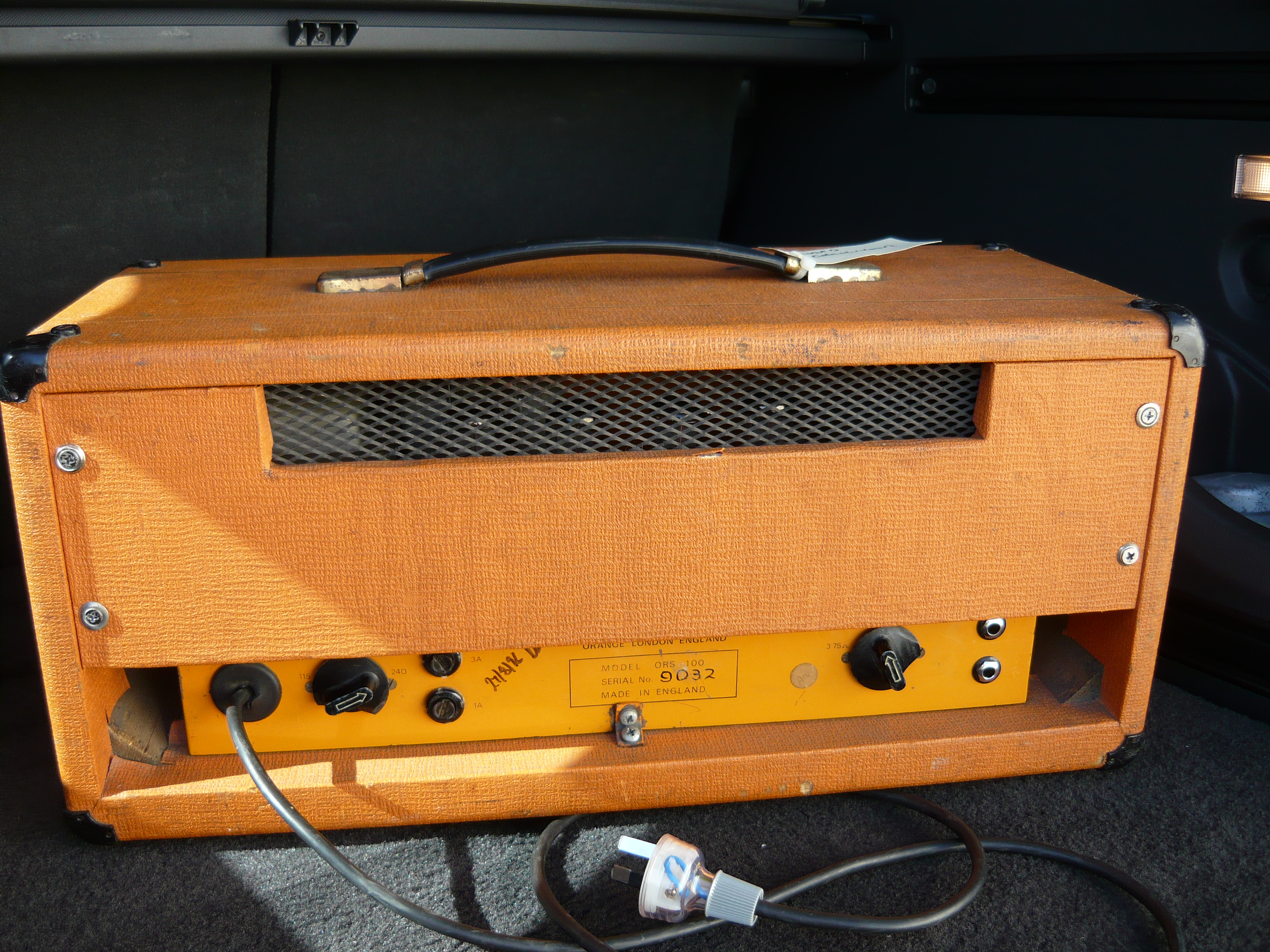
Orange Graphic 100
Dave contributed the Vadis/Galaxie amp that we blogged back in January 2012, which has been one of our most widely read blogs (for Australian readers). We have previously discussed the servicing of Orange amps back in April 2012, October 2011, & May 2011, but those amps were products of the contemporary Orange company. This is our first ever blog of an original Orange from 40 years ago.
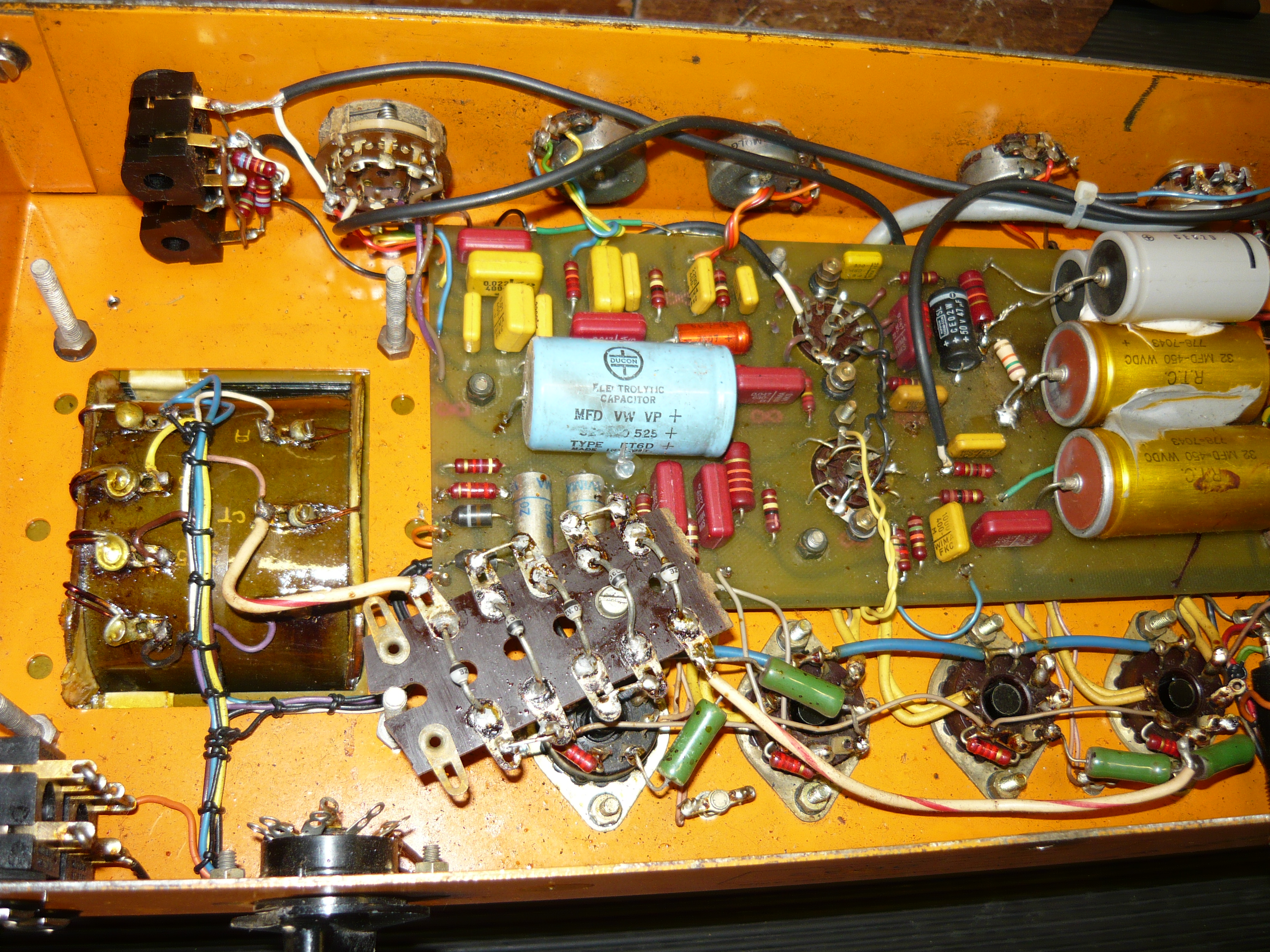
Orange Graphic 100 internal prior to overhaul
Any guitar amp this old will have numerous issues to be resolved, including electrical safety, some components (eg electrolytic capacitors) will be well past their use-by-date, and also there will have been repairs carried out on-the-run which may well have to be corrected to produce a stable amp which performs as originally intended.
This amp is designed to run its quad of EL34 power output valves at a very high 525V DC, similar to some very old Marshalls from that era. This places additional stress on modern production EL34’s, as well as being a potential source of problems for printed circuit board designs.
Orange Graphic 100 internal prior to overhaul
Sure enough, there had been a melt-down in this amp, probably many years ago, which resulted in permanent damage to the p.c.b., with some tracks & pads having lifted, required the circuit to be completed with wire links. This had been repaired reasonably well previously, and we carried out some additional repair work in this area. You can see from the photo immediately above, the amp had been modded with the addition of zener diodes to lower the EL34 screen grid voltage. Quite amazingly given the high DC volts, there was no bias adjustment available on this amp.

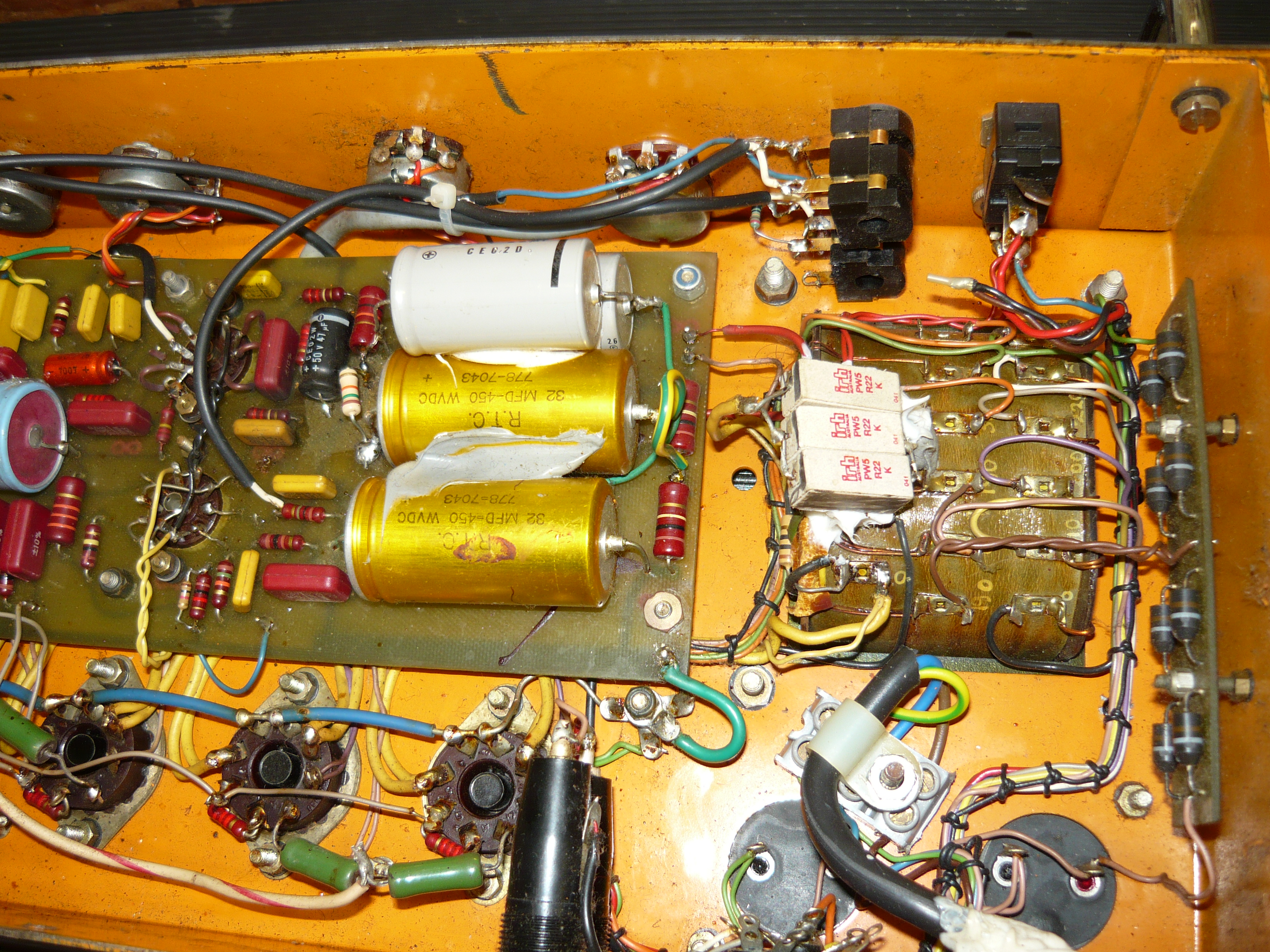
Orange Graphic 100 rear view of chassis prior to overhaul
Our agreed strategy was to restore the amp where possible to the original design, and update selected components, plus create an adjustable bias supply for the EL34’s. In Dave’s words: if you are able to drag the amp from being a potentially lethal museum piece & back to its former glory, then please proceed ! The trickiest bit was removing the p.c.b. from its position without introducing any more problems. These amps were really well made, built like a proverbial British tank, but employed single core wire, which as it ages becomes rather brittle and prone to breakage.

Orange Graphic 100 chassis front view prior to overhaul
We cleaned up the copper side of the board and replaced all 9 x electrolytic capacitors, together with some 2 watt carbon film resistors. We installed a bias trimpot in place of a fixed resistor, which gives a very broad range of adjustment, permitting the installation of various EL34 alternatives, eg E34L or KT77. We bedded down the high voltage capacitors in a blob of silicone for stability. We replaced the 4 x worn out pots and added an earth wire to the rear of the pots to improve shielding.
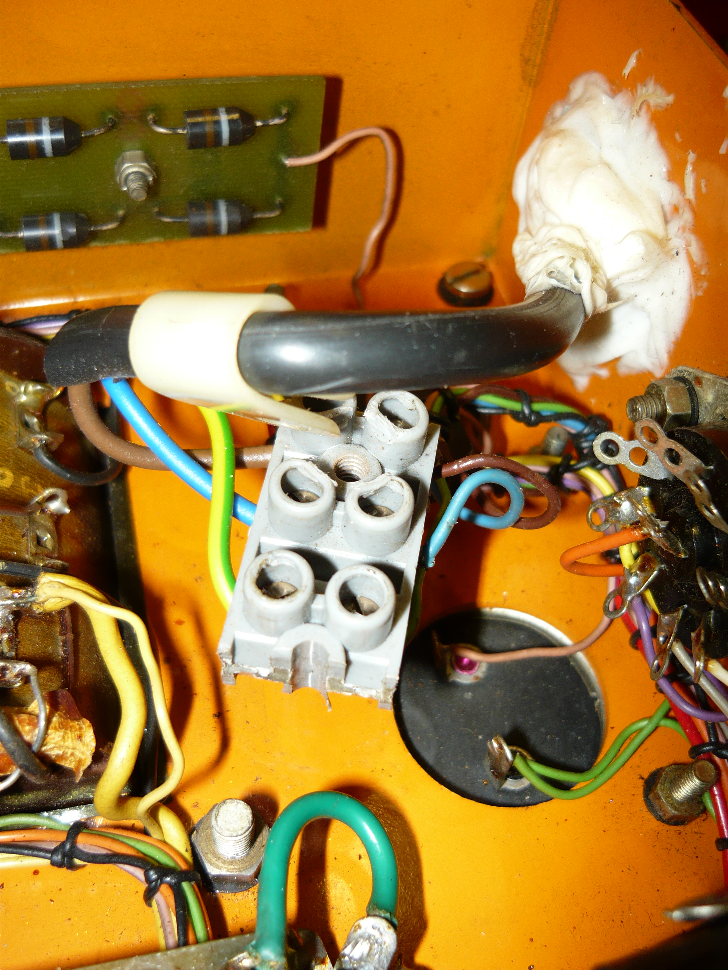
Orange Graphic 100 checking electrical safety issues
External to the board, the pair of vertical mounting 100uF/500V main power supply caps were replaced. All jacks & 9-pin valve sockets were cleaned with DeOxit. V1 & V2 were replaced with JJ 12AX7-s valves, which would be a reliable choice given the rather high cathode voltage in the V2 phase-splitter stage. The EL34’s tested OK and were retained. We found that the earth connection to the terminal block in the photo to the left had a stripped thread, which meant that the earth connection could not be tightened ! We replaced the terminal block and added a multi-strand earth wire connection direct to the chassis.

Orange Graphic 100 HV capacitors replaced & board repaired
One unusual feature of the ORS100 design, especially compared to the published schematics of vintage Orange amps available on the internet, is that the huge filter choke actually carries the entire HV current draw of the amp, not just the screen grids & preamp valves. This probably has a positive impact on the amp’s performance when driven into clipping. However, the down side is that the voltage on the EL34 screen grids is too high. As a general rule of thumb, the voltage on the screen grids should be lower than that on the anodes, so we increased the value of the 4 x screen grid resistors, and installed those W22 series enamel body resistors which are intended for the harshest conditions.

Orange Graphic 100 new capacitors plus bias trimpot installed
The customary earth shield between the input jacks & the output transformer connections was missing, presumably lost at an earlier unknown repair job. Given the proximity of the input jacks to high voltage (HV) wiring, this was a contributing factor to the amps instability issues. Luckily we had a suitable shield in stock which we had manufactured for our own Richards amps, and you can see it has been installed in the photo to the left. After hours of work we were finally in a position to carry out a PAT test and a power output test. The result was 30V/8 ohms = 112 watts @ onset of clipping.

Orange Graphic 100 repairs completed
What did the ORS100 sound like ? This amp is designed to be played loud ! We gave it a blast in the workshop, and the more we turned it up, the better it sounded. The treble, bass & presence controls are very effective, but we really preferred the 6-position FAC switch on maximum anti-clockwise for a maximum full-bodied tone. There may not be too many venues left where you can actually use this amp to its full capability.
This overhaul exceeded the original budget by quite a margin but Dave seemed to be very excited by his new amp acquisition. Here are Dave’s initial reactions to the amp as conveyed by text message:
HI Ivan – the Orange was wonderful, thanks ! Enormous sound. I love it !!
Once again the Orange was phenomenal at rehearsals. It’s my new favourite amp. I think it’s because it handles pedals so well too. I really, really love this amp & as always your work is top notch.
Thanks Dave, we love that kind of talk. IR.

December 14, 2013 at 3:57 pm |
On your repair to the Orange ORS100… The photo with the replaced 30mfd @ 500volt cap, is that the new trim pot ? The white item ?I think maybe the flash from the camera bleached out the visual details.
I just bought one of these amps and will be doing a cap job.
December 15, 2013 at 1:45 am |
Yes indeed: a trimpot has been installed in place of a fixed resistor in the bias voltage supply, which achieved the desired result without having to redesign the supply; the camera flash did wipe out the detail to some extent, but it is a good-quality cermet trimmer offering both screwdriver & finger adjustment; IR.
February 27, 2019 at 4:53 am |
Hi there!
I have the same model of amplifier at home(Funnily enough, mine is number 9033–one higher than the one here!)
I have a new quad of Mesa/Boogie EL34 tubes, and because this amplifier doesn’t offer any bias pot by default, would it be okay to just plug in my new EL34s?
The amp has been re-capped already it appears. It’s missing the earth shield like this one, so I may make one to put in or try to find one.
In case you were curious, here’s a photo of the guts of it: https://ibb.co/f9QmPN3
~Ely
February 27, 2019 at 9:17 am |
Interesting ! this example looks to be in much cleaner condition than the one I wrote about, which had experienced a couple of melt-downs in its career (still sounds phenomenal though); you really need that metal shield between input jacks and output transformer wiring; I would strongly recommend that you don’t simply install the EL34s without first having a strategy for correctly setting the bias – these amps run at very high DC voltage and therefore you may potentially destroy your nice new valves. IR.
December 28, 2024 at 3:21 am |
Great reading your blog ppost