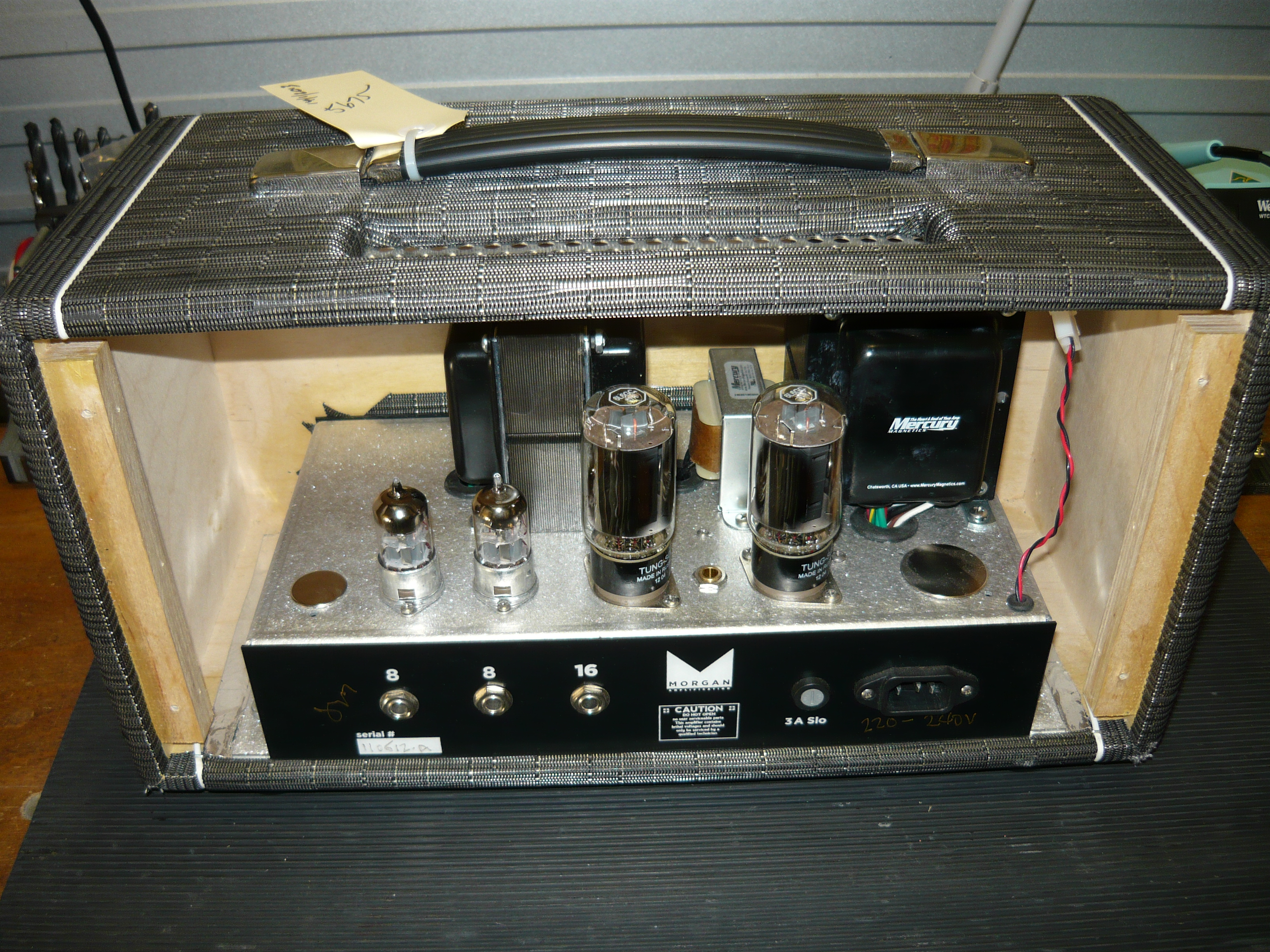
Rivera Jake Studio 1×12 combo
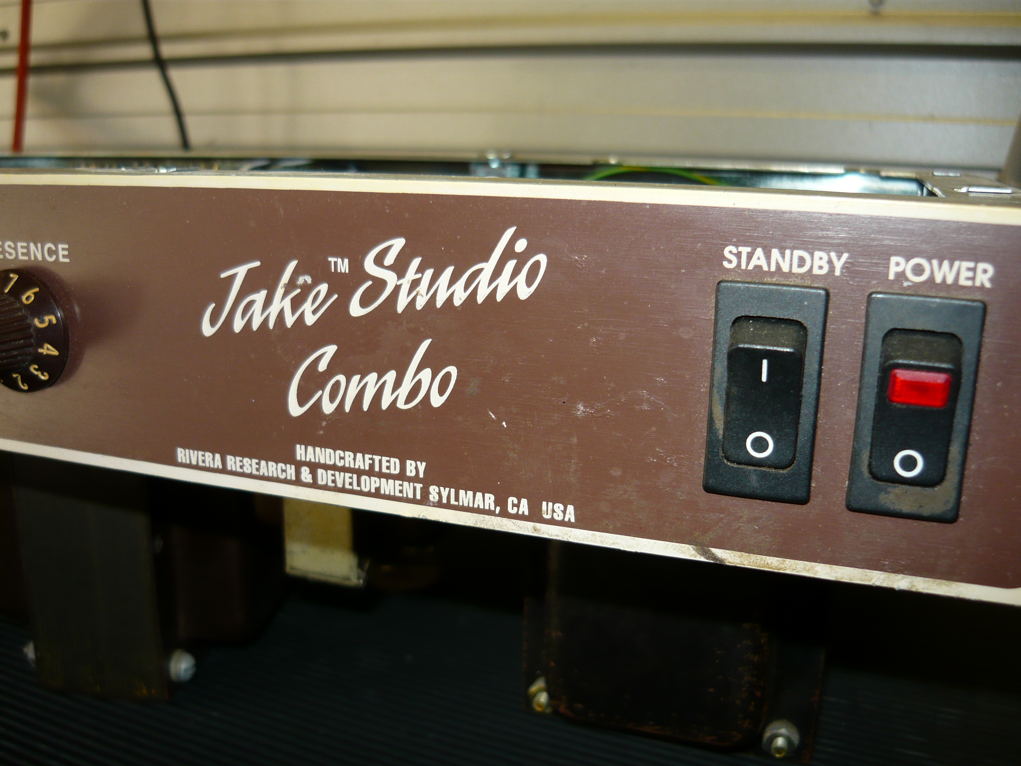
Hello again. In this week’s blog we revisit the amps of Paul Rivera. We previously published blogs re Rivera amps on Dec 16, 2011 (more about Rivera amps: the Ninja Boost MOD), Nov 4, 2011 (the Rivera Bonehead amp), and Jun 19, 2011 (do we cater for the jazz guitarist ?). There are now 65 blogs published, so there’s something there for all amp & pedal enthusiasts. The two amps we are discussing are the Rivera Jake Studio Combo, which we assume is named after a prominent American session player, and the Rivera Thirty Twelve, which is also a 1×12 combo.
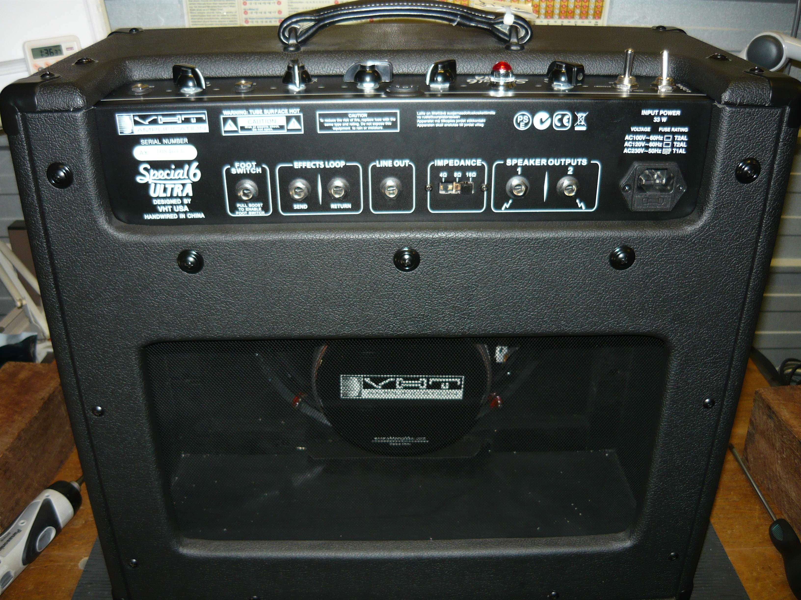
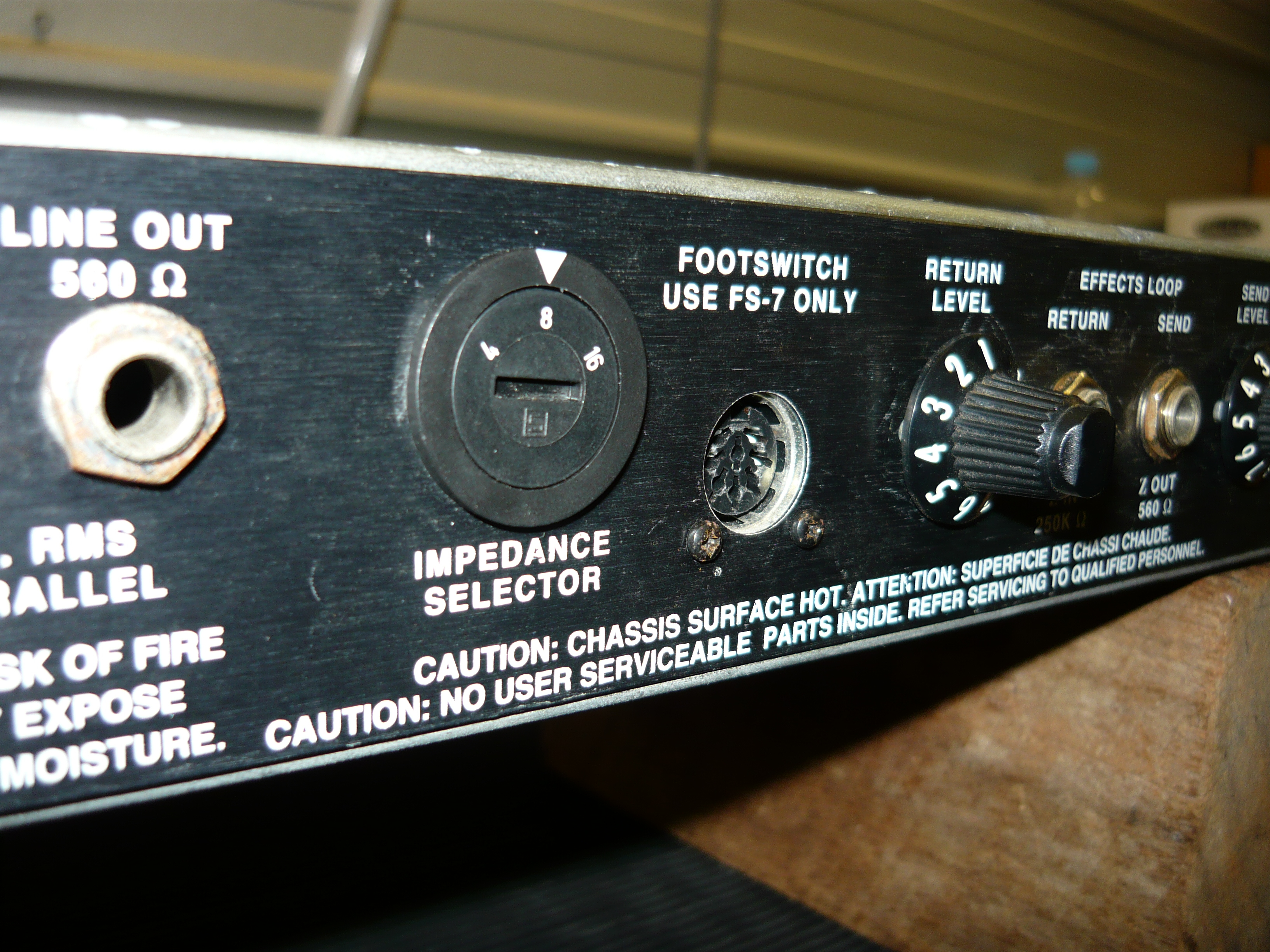 Our mission statement with the Jake was to replace the broken impedance selector switch, and install our now almost famous Ninja Boost MOD. You can see that the impedance selector is a rotary 3-position switch situated on the rear panel. Replacing the switch was pretty straightforward, but unless you want to MOD the rear panel, you have to source the exact switch from Rivera, via one of their distributors.
Jake Studio Combo Ninja MOD
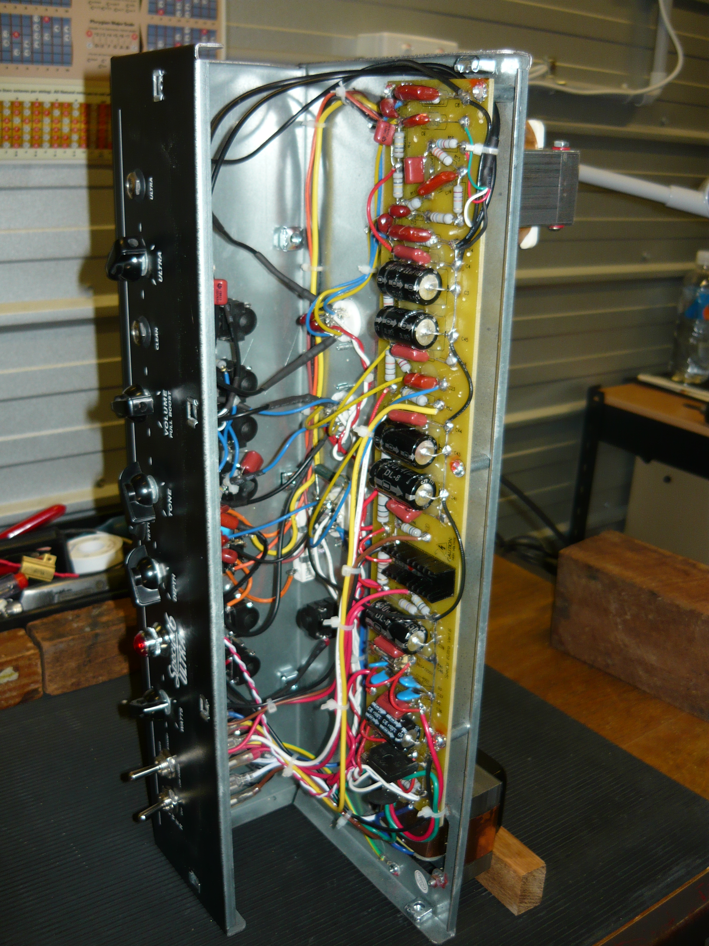
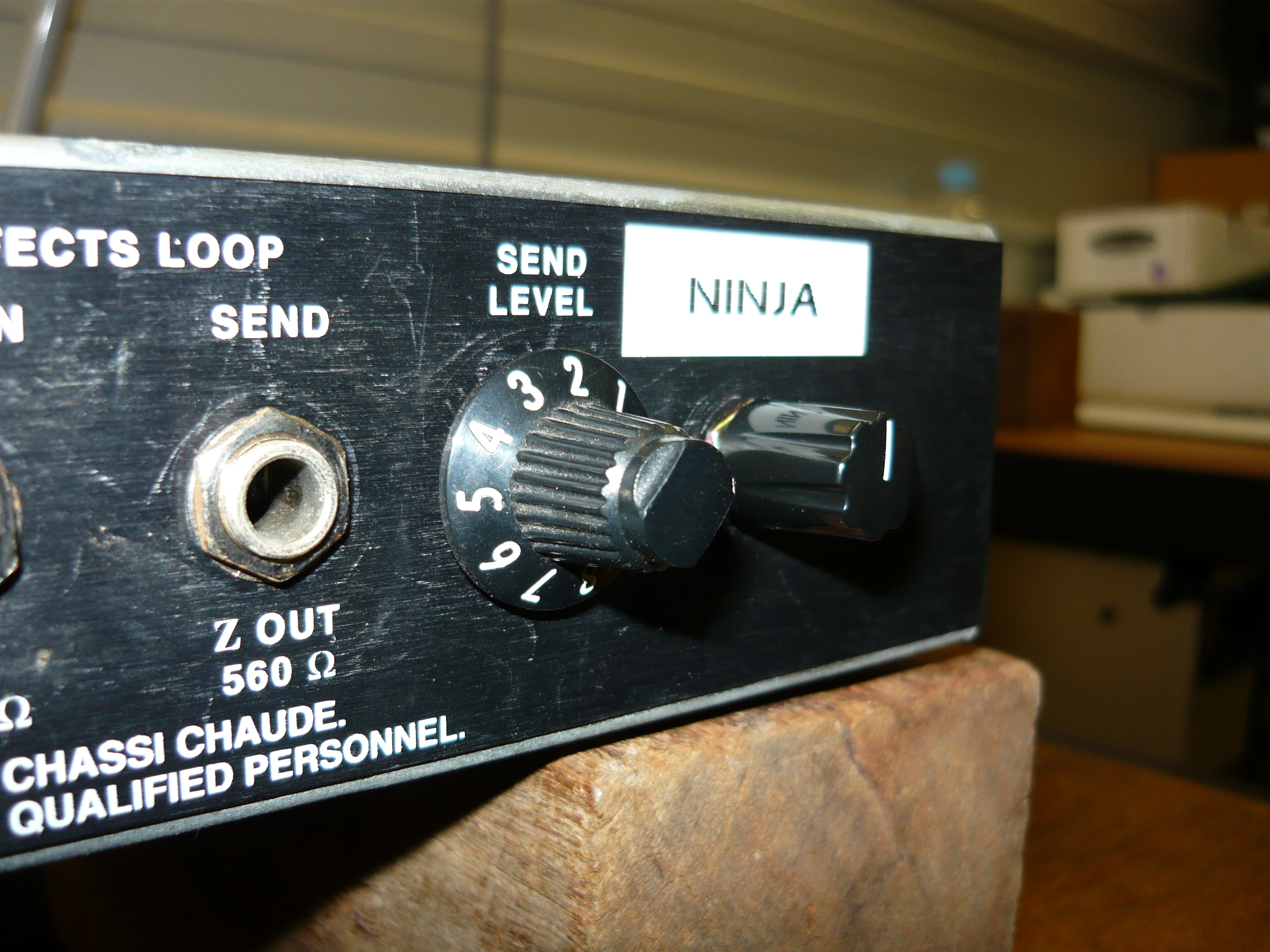
You can also see from the photos that there isn’t a whole lot of spare room on the rear panel of the Jake model, so we had to install the variable boost pot (potentiometer) in the remaining space betweeen the FX Loop and the end of the chassis. We are getting more proficient at implementing this MOD now, having now installed a few, in various models from the range. We always use highest quality shielded cable, in this case bedded down in a blob of silicone, to keep microphonics to an absolute minimum.

Ninja Boost MOD
Apart from a different location, this MOD was implemented in exactly the same way as in the other Rivera amps we have done, with the same very smoothly controllable boost function as the end result. The strap handle was dangerously worn so we automatically replaced that. The exposed metal strip could easily slice someone’s hand open.
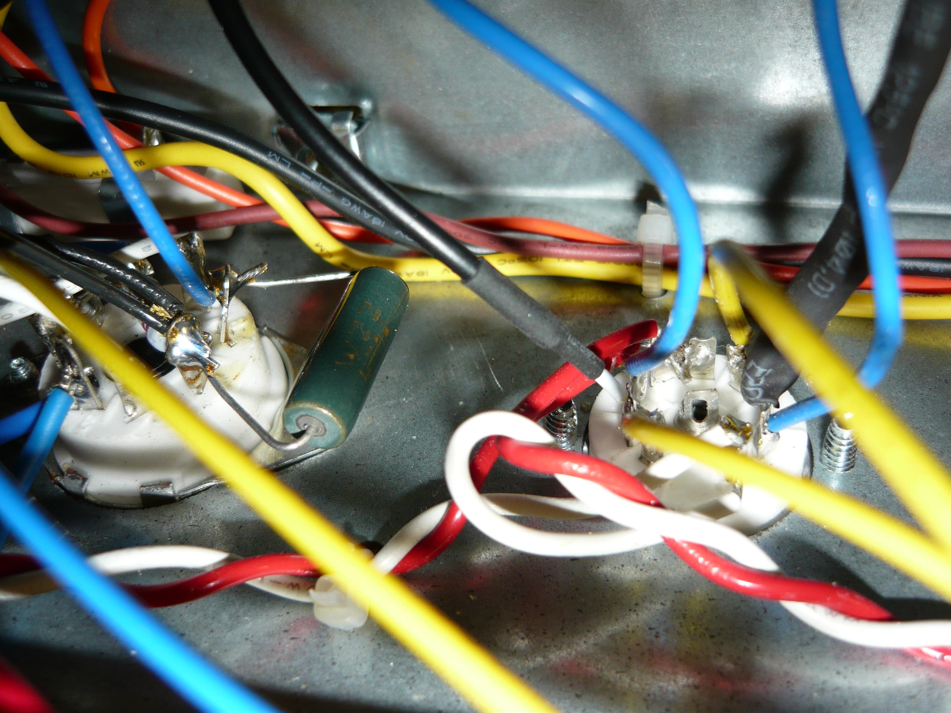
 To finish off the job, the pots needed cleaning with Faderlube and the input jacks (x2) were R/S, cutting in & out pretty badly. The best option was to replace them altogether. Unfortunately, the jacks are a printed circuit board (p.c.b.) mounting type, specific to Rivera amps. The jacks are earthed to the chassis as well, ie non insulated.

the slightly road worn Rivera Jake Studio Combo
We wanted to install the traditional heavy duty Switchcraft open construction jacks, as per vintage Fender amps, so we dispensed with the input jack p.c.b. altogether and hand-wired the new jacks. Perfect ! Both these combo’s feature the standard Rivera features of a USA-voiced preamp, a British-voiced preamp, a pull-boost on each preamp, an FX Loop and a reverb tank. It seems that there are relatively small differences in the circuit that differentiate the various models.

the Rivera 30/12
Our second example is the Rivera Thirty Twelve combo, and in this case a much more complex set of problems to resolve. The stated fault from our customer was the amp had gone low level, generating miscellaneous noises, plus the reverb & volume pots had suddenly gone very noisy ! Initially quite a bewildering set of symptoms. When we powered the amp up, we found nil output from either preamp, but some very low level output via the FX Return jack.
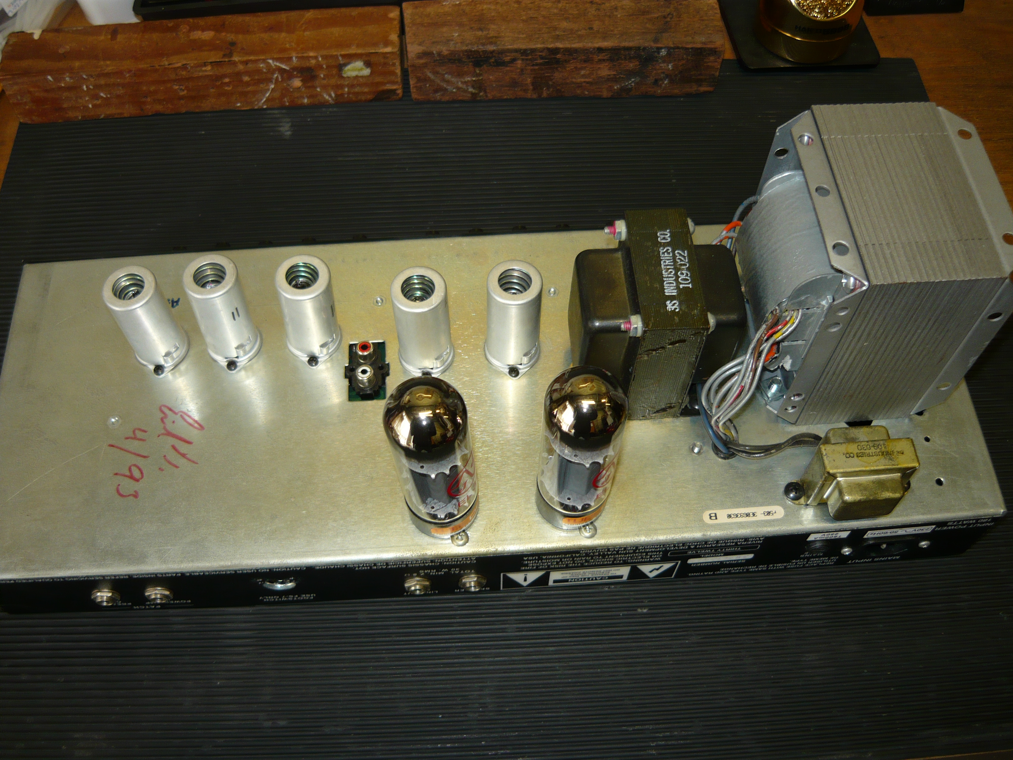
Rivera 30/12 chassis but not the correct power transformer
The 12AX7 preamp valves tested substandard and would have to be replaced, but this was not the main problem. The first thing we noticed after removing the chassis from the cab was the non-original power transformer ! It was huge, and presumably an Aussie-made unit that was installed by persons unknown after the original factory unit went faulty. There was evidence of considerable damage to the power supply end of the main p.c.b., with lifted pads & tracks, so there had been some sort of meltdown that went along with (or maybe caused) the transformer failure.

Rivera 30/12 main board
Some p.c.b. repairs had been attempted, but the results were not what you could describe as professional. We see some extremely inept repair attempts and this one is not the worst, but is well up there. The replacement power transformer actually looks more suited to a 100 watt amp. Remember, this is a 30 watt EL34 power amp and we are expecting to see a high voltage supply in the range of 380V to 400V DC maximum. This particular transformer was delivering over 500V DC, and yet no attempt had been made to upgrade the capacitor voltage ratings in the power supply circuitry, or configure pairs of capacitors in series to achieve the necessary voltage rating, plus the bias supply needed to be rejigged to give the wider range of bias adjustment required to compensate for the higher operating voltages. In other words, the amp was permanently under biased, resulting in very hot running output valves.

Rivera 30/12 low voltage power supply
The EL34 output valves were at the end of the road, as you would expect, so we supplied a new matched pair, as well as some selected 12AX7 preamp valves. We set about rebuilding the high voltage supply and the bias supply, within the constraints of a permanently damaged board. Installing series pairs of 350V DC caps is the simplest way of achieving a higher voltage rating. None of this exlains the complete lack of output from the preamps. The low voltage supply was also damaged – the regulated +18V supply rail was down to only a few volts. Replacing the +18V regulator IC did not make a huge improvement, so the next step was rebuilding the regulated and unregulated low voltage supplies.

rear view of reassembled amp
In case you’re wondering the significance of the low voltage supplies to a Rivera amp, the 12AX7 preamp valve heater filaments are powered in a relatively complex arrangement of series connections to the low volts supplies, as opposed to the more conventional parallel arrangement from a 6.3V AC supply. Each 12AX7 should read approx 12V DC across pins 4 & 5. Therefore losing the +18V DC rail was the reason for nil output from the preamps, ie several 12AX7’s were not functional under these conditions.

the Rivera 30/12 repairs completed !
Well, at the conclusion of several hours of work, we were able to bias the amp for a reasonable operating point @ 515V DC anode supply. Initially, on sine wave test into a dummy load, the output waveform was unstable, but we installed a 100pF/1kV cap across the anodes of the phase-inverter stage and that settled things down. The amp now delivers 20V into 8 ohms = 50 watts. Colin will have to take care not to blow the stock speaker which is only rated @ 35 watts. All functionality on this amp is now restored, we just hope the board holds up in the longer term for the customer.