the Pro Tube lead 100 head
Hello and welcome to the blog. Once again we have completed major repairs to a Laney (UK) “AOR Series” amplifier – model name Pro Tube Lead, this time a 100 watt head for customer Ben Rabey. We previously published blogs on 14/5/2013 and 10/7/2012 describing repairs and MODs to Laney amps in detail, including the AOR Series 50 watt combo, and also the LC30-II combo.

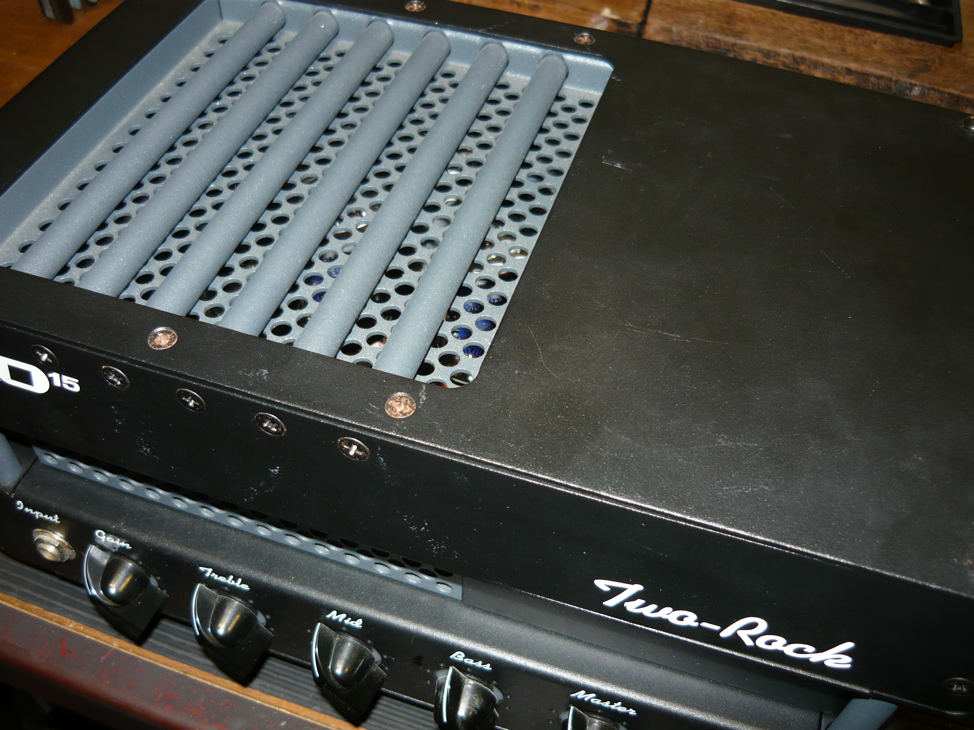
Pro Tube Lead 100 head sitting on a Hame speaker cab
The fault description from our customer was that the amp plays OK for a while, and then the output drops markedly ! Upon removing the chassis from its sleeve, the first things we noticed were that the mains fuseholder was loose and could not be tightened satisfactorily, plus the amp was seriously under-biased resulting in a much higher than normal current draw by the quartet of EL34 output valves (tubes).

removing and reinstalling the board is quite a task, but has to be done !
We replaced the fuseholder altogether with a current production unit that complies with contemporary electrical safety standards. We also installed the correct value HT fuse – T1A. Following this, the amp passed electrical safety testing to Workcover NSW standards. This is all important stuff, and should never be overlooked. We tested the quartet of EL34 valves and all the 12AX7 preamp valves externally to the amp with no apparent problems revealed.

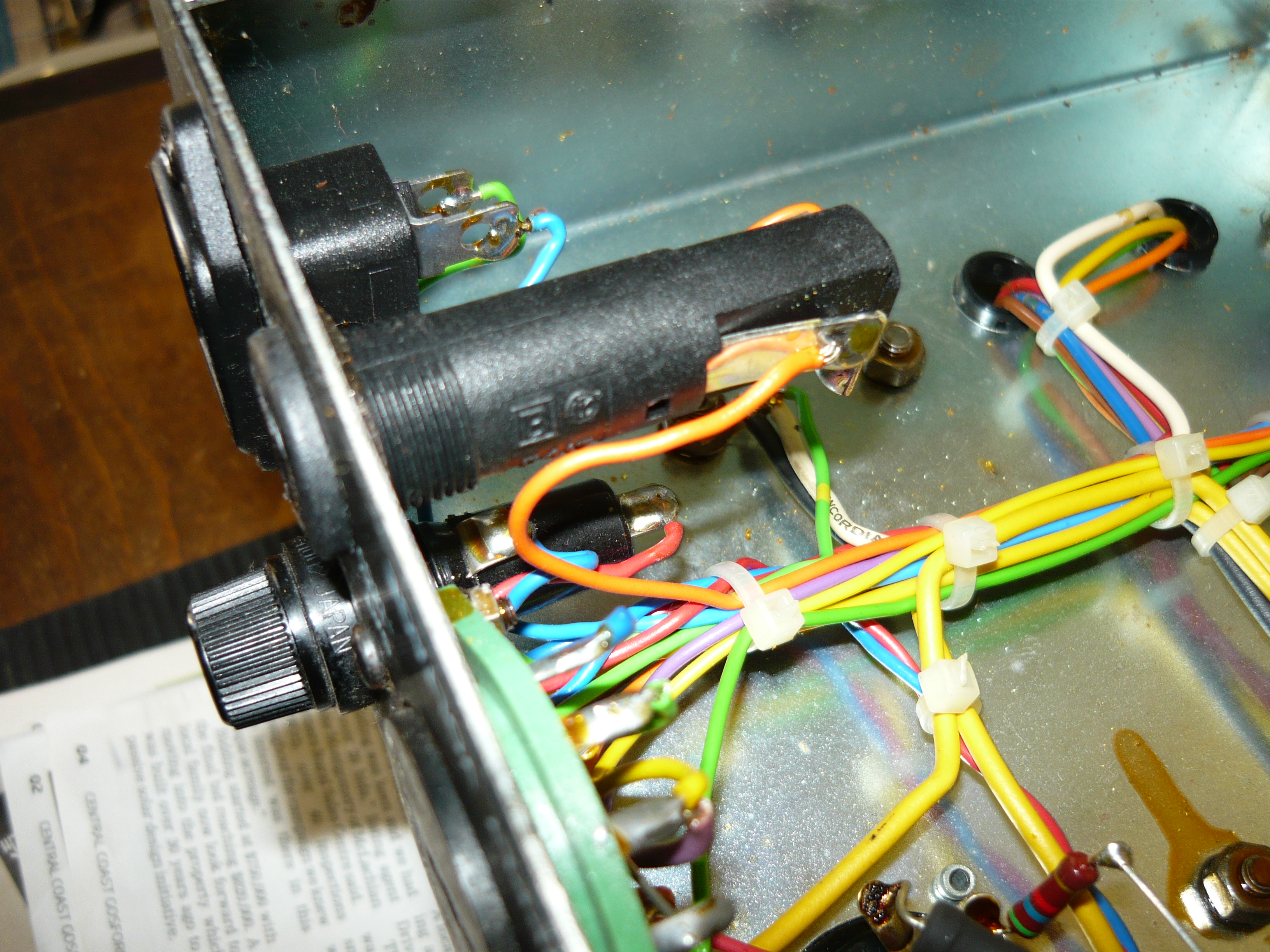
access to much of the wiring is under the board, but available space is very tight !
After re-installing the valves (tubes), we rebiased the EL34’s to a sensible current draw. The amp tested both very low and very distorted output signal into a dummy load. We observed a good drive signal to the EL34’s from the phase-inverter stage, with a signal injected at the FX Loop ‘return’ jack, so we had every reason to suspect that the output transformer had broken down internally. We quoted Ben on replacing the output transformer plus other tasks, and the project proceeded.

the new output transformer installed on the Laney chassis
As we are an authorised repairer for Marshall amplification, we therefore have access to the full stock of Marshall spares for current and vintage models. It just so happens that the 100W output transformer for the JCM800 series, designated C2668 (by Dagnall Electronics), is a perfect match and perfect fit for the 100W Laney. This is hardly a surprise, as the Laney is very obviously based on the JCM800 design, but with additional gain and additional features.

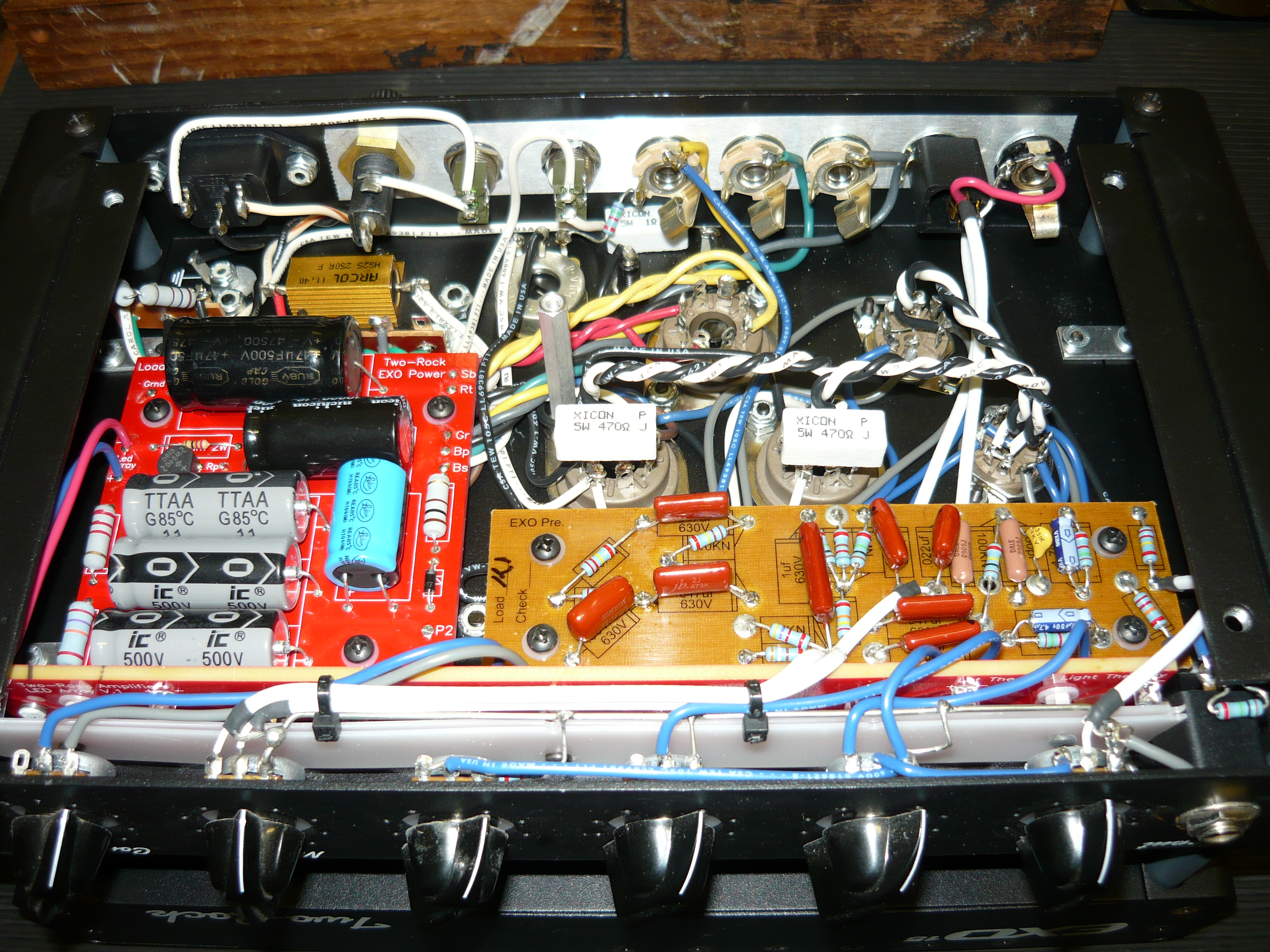
repairs completed and board reinstalled
Getting access to the wiring to carry out this task is not easy, as much of the wiring passes underneath the single large printed circuit board (PCB). Definitely not mil-spec wiring, but the JCM 800 amps are exactly the same (although their wiring is somewhat tidier). Removing the board requires removing a number of fasteners, plus also removing all the front panel controls, as all these controls are hard-wired to the board, as you would expect.
new ‘touch proof’ mains fuse installed
The replacement C2668 transformer wiring of course has a completely different colour code to the original Laney unit, which required some additional investigation to complete the installation successfully. While we had both sides of the board exposed, this was the perfect opportunity to replace the bias supply filter caps, plus some of the low-voltage supply components (as per the previous Pro Tube Lead repair job). You can see a burn mark on the component side of the board under a power resistor in the low-voltage supply, so this appears to be a common problem in these amps.
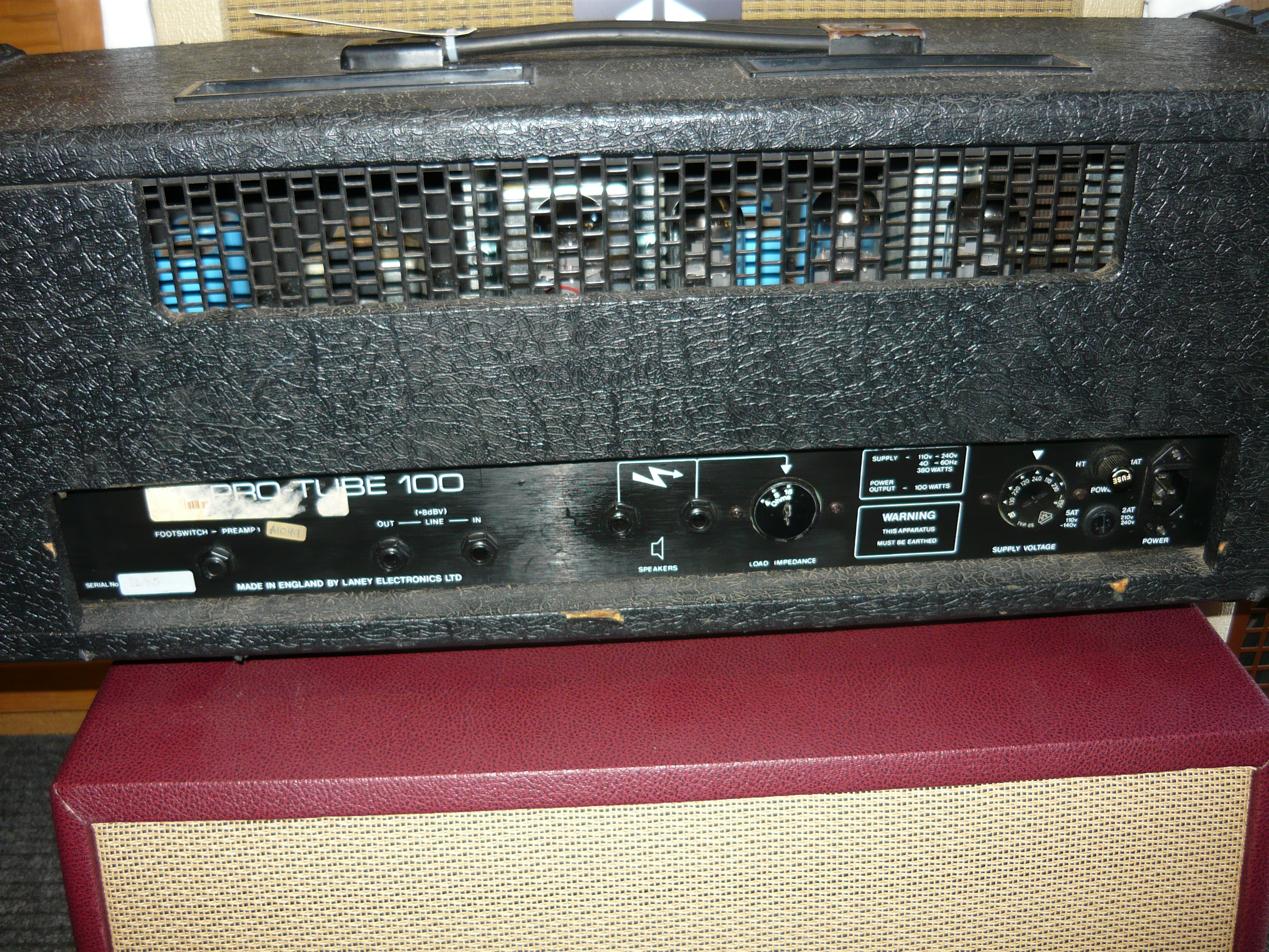
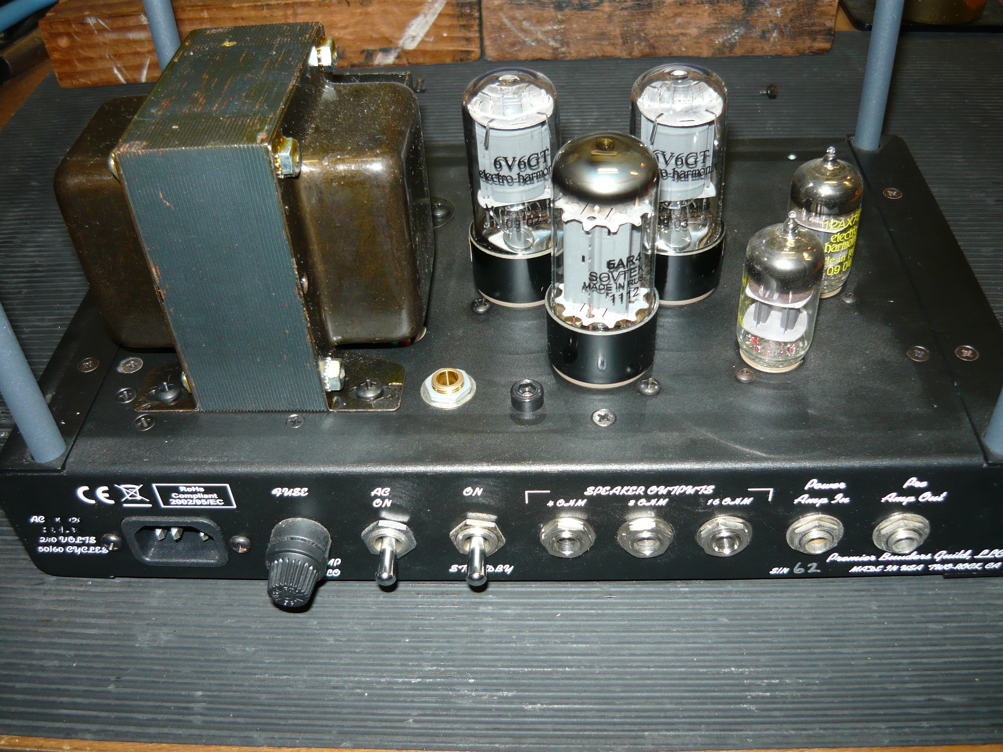
rear view Laney 100W head
For those interested in technical matters, this amp was serial # 2685, and appears to have been built in 1988. After installation of the new transformer and rebias of output valves (tubes), we had a high-tension voltage supply of just under +470V, and a bias voltage of -38V. The amp delivered 43V into 16 ohms @ the onset of clipping = 115 watts. Was the blown audio output transformer a direct result of the under-biased output valves ? We will never know – sometimes these are just random events. Many thanks to Ben for his continued custom. As always with these models – once set up and running properly the amp sounded huge ! IR.