
Peavey Valve King 100
Hello. This week we received at the workshop one of the more recent Peavey made-in-China valve amp heads for repair. One of the ‘Valve King’ models, this is the VK100. Stated fault was – the amp just stopped. We have been repairing Peavey amps since the 1980’s, by the way, including warranty work, but we have noticed a steady decline in the serviceability of their amps and will only accept non-warranty repairs these days.
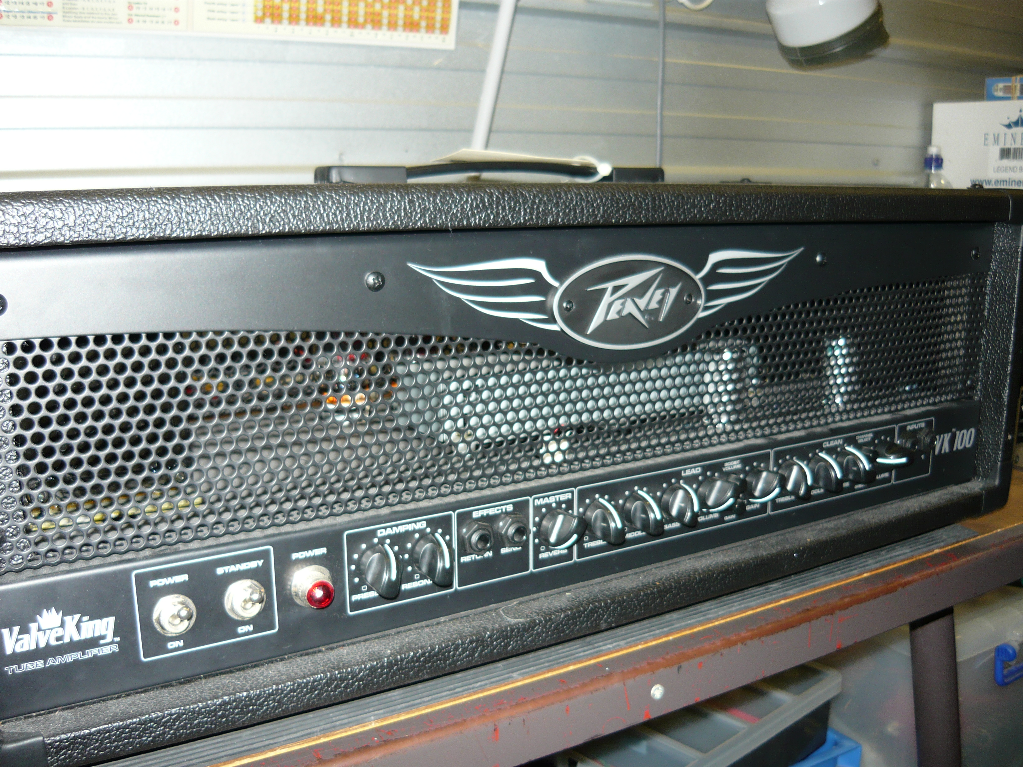
Valve King 100 head
The amp indeed would not power up, and examination of the mains fuse, actually the only external fuse, revealed that it had not blown, so the next step was remove the chassis from its sleeve. The fuse for the HT (high voltage) supply, F201, is located on the main p.c.b. Obviously one or more of the 6L6GC power output valves had gone S/C (short-circuit), causing the HT fuse to blow.

Valve King 100 head
Unfortunately, F201 is a miniature glass fuse directly soldered into the p.c.b. (printed circuit board), so easy replacement is out of the question – the board has to be stripped out, ie removing all control knobs, nuts, screws, etc. Is this for real ?? As this fuse is likely to blow several times during the life of this amp, the first MOD we will implement is to wire the fuse to an external fuseholder on the chassis rear panel, easily accessible to all. The HT fuse is T1.6A. You can see this MOD completed in the photos, plus the Dymo labelling.

Valve King circuit boards
One of Peavey’s favourite design tricks is to wire the valve (tube) heater filaments in series rather than parallel, even including the output valves. There can be various combinations of series heater arrangements in the one amp. Without a detailed schematic diagram on hand, this can be very confusing, especially in amps with a higher number of valves, eg the 6505 combo. Basically, if you remove any valve from its socket, the other valves (or possibly just some of them) will not power up. For each Peavey model, we build up a file of such idiosyncrasies so that we don’t get caught out twice.

HT fuse MOD has been implemented
So, we have reached the point when we intend to install a matched quad of JJ 6L6GC output valves. These valves should sound very good in this style of amp. The next logical step after installing any output valves is to rebias the amp. However, the bias supply in this amp is not adjustable, nor is there any provision to monitor the current draw of the 6L6’s. HUH ?? The idea that anyone would design a 100 watt valve amp with a non-adjustable bias supply in this day & age is beyond comprehension, but that is the situation with the VK100.

miniature pcb fuses & bias resistor MOD
The amp initially appeared to be slightly under-biased, so we replaced R211 with a different value which resulted in a correctly biased quad of JJ’s. Next time this amp comes in, we will install a 25-turn trimpot in place of R205, which will solve the problem once and for all. We also installed 470K resistors across high voltage supply capacitors C202 & C204, as these caps were holding their charge (nearly 500V DC) long after the amp was switched off, complicating the service job. This has no effect at all from the customer’s point of view, but makes life easier for the next service tech.

VK100 rear panel
The remaining tasks are an electrical safety test (PAT test), power output test and burn-in test, with a final play test to complete the job. The amp delivered 30V into an 8 ohm resistive load, which translates to 112 watts. When we first attempted a power output test, we couldn’t get a good clean sine wave output, even from injecting our test signal at the FX Loop ‘return’ jack. This was most perplexing, until we discovered the mysterious Texture pot on the rear panel, near the speaker jacks.
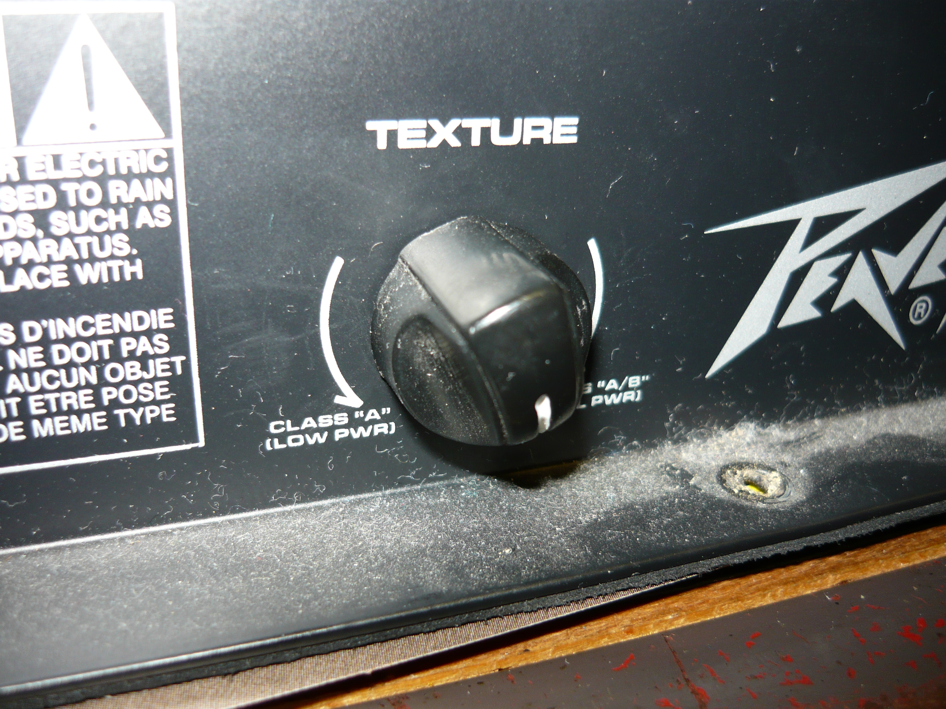
the mysterious ‘Texture’ control
The Texture control claims to sweep the power amp from Class-A (c.c.w.) to Class-A/B (c.w.) mode of operation. This is complete nonsense ! What it actually does is convert the amp from normal push-pull (Class A/B) operation to a kind of quasi single-ended mode by shunting away some of the signal from one of the two outputs of the phase-splitter stage to ground. This only roughly approximates the behaviour of a single ended amp and naturally the resulting waveform is somewhat distorted, which is what caused our initial confusion. The only way to carry out a meaningful sine wave test is to set the Texture control to fully clockwise (c.w.). Well, how does the amp sound with a decent set of valves ? Not too bad actually – the ‘clean’ channel sounds very Fendery, with a slightly different EQ sweep, and the ‘lead gain’ channel actually starts off with considerable distortion levels, so any kind of ‘crunch’ tones are just about impossible, but will probably please the younger guys, and the reverb is also pretty good for a short tank driven by IC’s rather than valves. We also provide world-class service to the Peavey EVH amps and the well known Classic 30/Classic 50 models. Thanks for checking in to the blog – I.R.

