Archive for May, 2013

MODS to the Marshall JTM600/JCM600 series amps

May 19, 2013
JCM600 range from Marshall website

JCM600 range from Marshall website

We are now implementing mods & upgrades to a broad selection of guitar & bass amplification, primarily valve (tube) but occasionally solid-state as well. The most common examples are the Fender Pro-Junior & Blues Junior models, however we have been selectively modding Marshall amps since the 1980’s. In this blog we have a quick look at the Marshall JTM600 & JCM600 series amps – it would appear that the differences between the two are limited to cosmetics & choice of speakers, the electronics remains the same for both series.

JCM600 combo

JCM600 combo

These amps remain among the more obscure of Marshall’s amp offerings of the last 20 years or so, very few guitarists would have played through one of them, let alone owned one. We do have a few Central Coast (NSW) customers that quite enjoy these amps, including “Gazebo”, the man who inspired this blog by commissioning us to mod his JTM60 amp head (we modded the “clean” channel only).

JCM601 model

JCM601 model

These amps don’t have a great reputation for reliability. We have replaced several transformers over the years, for example. The first batch of JTM600’s were blowing the main high voltage filter capacitors during the warranty period, although this problem has obviously been resolved. They are not particularly easy to work on – getting the circuit boards out and re-installing them is quite time consuming. Operating the EL34 power output valves (tubes) in the horizontal plane rather than the more conventional vertical plane is just asking for trouble. You have to choose your EL34’s carefully – with some brands there is the potential for an internal short-circuit to occur, if the heater filament sags for example. Please note, this is not normally a problem with the 12AX7 preamp valves. Regardless of your choice of valves, most of the heat from the power output valves goes straight up into the amp.

the JTM30 combo

the JTM30 combo

Over the years, we have tried to come up with ways to “bullet proof” these amps. Not all EL34’s like high voltages on the screen grids, for example. Installing a small DC powered cooling fan may assist the issue of heat build up within the chassis. The JTM30 model has presented less problems, but has one stupid design mistake – a non adjustable bias supply voltage, which complicates replacing the 5881 output valves unnecessarily.

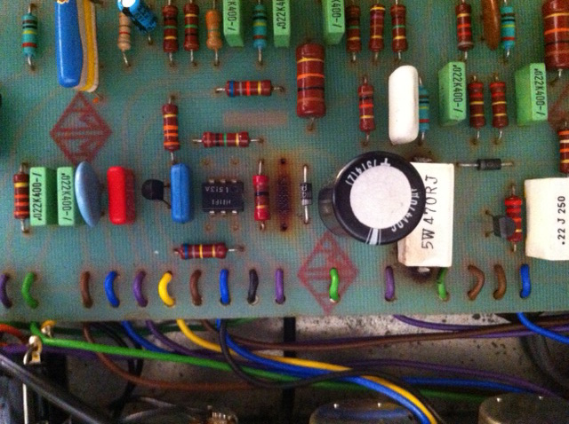
Stock, the 60 watt amps sound a bit thin and a bit sterile. The “lead” channel develops a type of distortion that sounds like it came from a stompbox, rather than from a valve amp. The main focus of our mods is to convert the “clean” channel to a circuit sounding as close as possible to a Marshall model 1987, ie a blues/crunchy tone with more fat bottom end and crisp high end. This is achieved by substituting selected components (resistors/capacitors) with more traditional “plexi” circuit values. This is what we achieved for “Gazebo” just this week. Once the job was completed, the “clean” channel was suddenly very useable for many styles.

With the “lead” channel you could easily go overboard, spending hours rebuilding the whole circuit. The simplest approach would be to remove the clipping diodes for a more natural valve (tube) medium distorted tone, although having done this it may be necessary to make some changes to balance the circuit for the now much higher signal levels.

Modding the clean channel as described, plus limited mods to the lead channel is a cost effective way to significantly improve the performance of these amps. We need to allow a minimum of 2 hours labour for this work, plus materials. We would have to quote re specific improvements to the power amp, eg adding a cooling fan, etc. Regards – I.R.

Repairs to the Laney AOR Series ‘Pro Tube Lead’

May 14, 2013
Laney AOR50 1x12 combo

Laney AOR50 1×12 combo

This Laney 50 watt 1X12 combo, designated the Pro Tube Lead model, was part of Laney’s AOR series valve amplifiers, manufactured in the 1980’s. Basically, these amps are Laney’s answer to the Marshall JMP & JCM800 series master-volume amps, but with some additional features including ‘pull-boost’ on some controls plus a footswitchable gain boost. The combo model also incorporates reverb (solid-state driven). There is more gain available than in a standard JMP or JCM800.

Laney AOR50 rear view

Laney AOR50 rear view

You can see the speaker in this combo is in its own sealed cab, which gives the amp a more solid ‘bottom end’ than a conventional open back, but which also makes the amp more directional. These amps are very loud !


problems on the board are causing our hum

problems on the board are causing our hum

Chris Jones delivered this amp to us from the ‘Blue Mountains’ (a beautiful location west of Sydney, Australia) – the problem was that a huge hum/buzz was ever present in the output. Some previous repair work had been done by a music shop with no improvement, and Chris, possessing some electrical know-how, had also attempted to isolate the problem. The scope of this repair job also included a valve replacement/upgrade, and also replacing some ageing high-voltage electrolytic capacitors. There was also an electrical safety issue, ref a loose fuseholder on the rear panel, which we replaced with a more robust type. The photographs were taken by Chris, by the way.

low voltage power supply faults on this board

low voltage power supply faults on this board

Upgrading the valves (tubes) and selected components in the high voltage circuitry did nothing to cure the hum problem. We next examined the low voltage power supplies. The +/- 15V DC rails that power the IC’s ref the reverb & FX Loop circuitry were unbalanced, so clearly could be a source of hum entering the signal path. We rebuilt the +/- 15V rails by replacing the zener diodes and filter caps.

There is yet another (single-ended) low voltage DC supply which powers the switching circuitry. This is another possible source of hum entering the signal path, and in fact turned out to be the main culprit. We noticed that the DC rail powering the switching was reading much higher than the schematics indicated. We also noticed differences between component values as listed on the schematic and what was actually on the board ! We rebuilt this low voltage supply strictly as per the schematic, and the voltage readings were now correct, plus there was an absence of hum ! We were quite concerned that the switching IC’s might have been damaged by the over-voltage, but the amp’s switching functionality checked out fine.

These repairs to the Laney AOR50 were happily completed successfully and on budget, allowing for an estimated 3 hours labour, plus parts as required. The wiring and assembly in the Laney is much rougher and untidier than the equivalent JCM800. To get to the copper side of the p.c.b., all the front panel controls have to be disassembled in order to flip the board over, but it has to be done for a neat job that will hold up over time. For collectors of 70’s & 80’s Brit valve guitar amps, this model is worthy of your consideration. Here are a couple of comments received from Chris after he took possession of the repaired amp……………..

I just tried her out, it’s the best it’s ever sounded, I would have liked you to try it out wound right up with the boost pulled, it’s unbelievably loud.

Hi Ivan, well I’ve put a few hours on it today, ran perfect, no hint of any problems. I can’t believe how good it sounds, I can see why they (Laney AOR) are very popular nowadays.

service & mods to the Peavey ‘Valve King’ 100 amplifier

May 9, 2013
Peavey Valve King 100

Peavey Valve King 100

Hello. This week we received at the workshop one of the more recent Peavey made-in-China valve amp heads for repair. One of the ‘Valve King’ models, this is the VK100. Stated fault was – the amp just stopped. We have been repairing Peavey amps since the 1980’s, by the way, including warranty work, but we have noticed a steady decline in the serviceability of their amps and will only accept non-warranty repairs these days.

Valve King 100 head

Valve King 100 head

The amp indeed would not power up, and examination of the mains fuse, actually the only external fuse, revealed that it had not blown, so the next step was remove the chassis from its sleeve. The fuse for the HT (high voltage) supply, F201, is located on the main p.c.b. Obviously one or more of the 6L6GC power output valves had gone S/C (short-circuit), causing the HT fuse to blow.

Valve King 100 head

Valve King 100 head

Unfortunately, F201 is a miniature glass fuse directly soldered into the p.c.b. (printed circuit board), so easy replacement is out of the question – the board has to be stripped out, ie removing all control knobs, nuts, screws, etc. Is this for real ?? As this fuse is likely to blow several times during the life of this amp, the first MOD we will implement is to wire the fuse to an external fuseholder on the chassis rear panel, easily accessible to all. The HT fuse is T1.6A. You can see this MOD completed in the photos, plus the Dymo labelling.

Valve King circuit boards

Valve King circuit boards

One of Peavey’s favourite design tricks is to wire the valve (tube) heater filaments in series rather than parallel, even including the output valves. There can be various combinations of series heater arrangements in the one amp. Without a detailed schematic diagram on hand, this can be very confusing, especially in amps with a higher number of valves, eg the 6505 combo. Basically, if you remove any valve from its socket, the other valves (or possibly just some of them) will not power up. For each Peavey model, we build up a file of such idiosyncrasies so that we don’t get caught out twice.

HT fuse MOD has been implemented

HT fuse MOD has been implemented

So, we have reached the point when we intend to install a matched quad of JJ 6L6GC output valves. These valves should sound very good in this style of amp. The next logical step after installing any output valves is to rebias the amp. However, the bias supply in this amp is not adjustable, nor is there any provision to monitor the current draw of the 6L6’s. HUH ?? The idea that anyone would design a 100 watt valve amp with a non-adjustable bias supply in this day & age is beyond comprehension, but that is the situation with the VK100.

miniature pcb fuses & bias resistor MOD

miniature pcb fuses & bias resistor MOD

The amp initially appeared to be slightly under-biased, so we replaced R211 with a different value which resulted in a correctly biased quad of JJ’s. Next time this amp comes in, we will install a 25-turn trimpot in place of R205, which will solve the problem once and for all. We also installed 470K resistors across high voltage supply capacitors C202 & C204, as these caps were holding their charge (nearly 500V DC) long after the amp was switched off, complicating the service job. This has no effect at all from the customer’s point of view, but makes life easier for the next service tech.

VK100 rear panel

VK100 rear panel

The remaining tasks are an electrical safety test (PAT test), power output test and burn-in test, with a final play test to complete the job. The amp delivered 30V into an 8 ohm resistive load, which translates to 112 watts. When we first attempted a power output test, we couldn’t get a good clean sine wave output, even from injecting our test signal at the FX Loop ‘return’ jack. This was most perplexing, until we discovered the mysterious Texture pot on the rear panel, near the speaker jacks.

the mysterious 'Texture' control

the mysterious ‘Texture’ control

The Texture control claims to sweep the power amp from Class-A (c.c.w.) to Class-A/B (c.w.) mode of operation. This is complete nonsense ! What it actually does is convert the amp from normal push-pull (Class A/B) operation to a kind of quasi single-ended mode by shunting away some of the signal from one of the two outputs of the phase-splitter stage to ground. This only roughly approximates the behaviour of a single ended amp and naturally the resulting waveform is somewhat distorted, which is what caused our initial confusion. The only way to carry out a meaningful sine wave test is to set the Texture control to fully clockwise (c.w.). Well, how does the amp sound with a decent set of valves ? Not too bad actually – the ‘clean’ channel sounds very Fendery, with a slightly different EQ sweep, and the ‘lead gain’ channel actually starts off with considerable distortion levels, so any kind of ‘crunch’ tones are just about impossible, but will probably please the younger guys, and the reverb is also pretty good for a short tank driven by IC’s rather than valves. We also provide world-class service to the Peavey EVH amps and the well known Classic 30/Classic 50 models. Thanks for checking in to the blog – I.R.